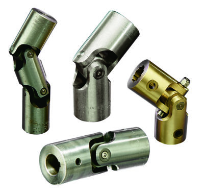
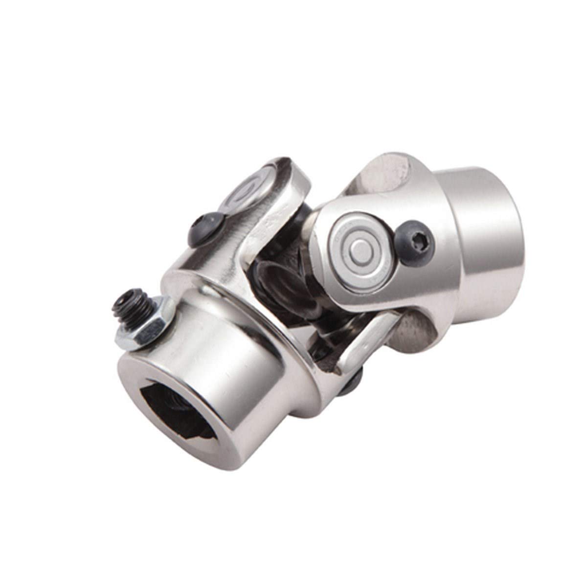
Product Description
| Spicer | P (mm) | R (mm) | Caterpillar | Precision | Rockwell | GKN | Alloy | Neapcon | Serie | Bearing type |
| 5-2002X | 33.34 | 79 | 644683 | 951 | CP2002 | HS520 | 1-2171 | 2C | 4LWT | |
| 5-2117X | 33.34 | 79 | 316117 | 994 | HS521 | 1-2186 | 2C | 4LWD | ||
| 5-2116X | 33.34 | 79 | 6S6902 | 952 | CP2116 | 1063 | 2C | 2LWT,2LWD | ||
| 5-3000X | 36.5 | 90.4 | 5D9153 | 536 | HS530 | 1711 | 3-3152 | 3C | 4LWT | |
| 5-3014X | 36.5 | 90.4 | 9K1976 | 535 | HS532 | 3C | 2LWT,2LWD | |||
| 5-4143X | 36.5 | 108 | 6K 0571 | 969 | HS545 | 1689 | 3-4143 | 4C | 4HWD | |
| 5-4002X | 36.5 | 108 | 6F7160 | 540 | CP4002 | HS540 | 1703 | 3-4138 | 4C | 4LWT |
| 5-4123X | 36.5 | 108 | 9K3969 | 541 | CP4101 | HS542 | 1704 | 3-4123 | 4C | 2LWT,2LWD |
| 5-4140X | 36.5 | 108 | 5M800 | 929 | CP4130 | HS543 | 3-4140 | 4C | 2LWT,2HWD | |
| 5-1405X | 36.5 | 108 | 549 | 1708 | 4C | 4LWD | ||||
| 5-4141X | 36.5 | 108 | 7M2695 | 996 | 4C | 2LWD,2HWD | ||||
| 5-5177X | 42.88 | 115.06 | 2K3631 | 968 | CP5177 | HS555 | 1728 | 4-5177 | 5C | 4HWD |
| 5-5000X | 42.88 | 115.06 | 7J5251 | 550 | CP5122 | HS550 | 1720 | 4-5122 | 5C | 4LWT |
| 5-5121X | 42.88 | 115.06 | 7J5245 | 552 | CP5101 | HS552 | 1721 | 4-5127 | 5C | 2LWT,2LWD |
| 5-5173X | 42.88 | 115.06 | 933 | HS553 | 1722 | 4-5173 | 5C | 2LWT,2HWD | ||
| 5-5000X | 42.88 | 115.06 | 999 | 5C | 4HWD | |||||
| 5-5139X | 42.88 | 115.06 | 5C | 2LWD,2HWD | ||||||
| 5-6102X | 42.88 | 140.46 | 643633 | 563 | CP62N-13 | HS563 | 1822 | 4-6114 | 6C | 2LWT,2HWD |
| 5-6000X | 42.88 | 140.46 | 641152 | 560 | CP62N-47 | HS560 | 1820 | 4-6143 | 6C | 4LWT |
| 5-6106X | 42.88 | 140.46 | 1S9670 | 905 | CP62N-49 | HS565 | 1826 | 4-6128 | 6C | 4HWD |
| G5-6103X | 42.88 | 140.46 | 564 | 1823 | 4-6103 | 6C | 2LWT,2LWD | |||
| G5-6104X | 42.88 | 140.46 | 566 | 1824 | 4-6104 | 6C | 4LWD | |||
| G5-6149X | 42.88 | 140.46 | 6C | 2LWD,2HWD | ||||||
| 5-7105X | 49.2 | 148.38 | 6H2577 | 927 | CP72N-31 | HS575 | 1840 | 5-7126 | 7C | 4HWD |
| 5-7000X | 49.2 | 148.32 | 8F7719 | 570 | CP72N-32 | HS570 | 1841 | 5-7205 | 7C | 4LWT |
| 5-7202X | 49.2 | 148.38 | 7J5242 | 574 | CP72N-33 | HS573 | 1843 | 5-7207 | 7C | 2LWT,2HWD |
| 5-7203X | 49.2 | 148.38 | 575 | CP72N-55 | 5-7208 | 7C | 4LWD | |||
| 5-7206X | 49.2 | 148.38 | 572 | CP72N-34 | 1842 | 5-7206 | 7C | 2LWT,2LWD | ||
| 5-7204X | 49.2 | 148.38 | 576 | CP72N-57 | 5-7209 | 7C | 2LWD,2HWD | |||
| 5-8105X | 49.2 | 206.32 | 6H2579 | 928 | CP78WB-2 | HS585 | 1850 | 6-8113 | 8C | 4HWD |
| 5-8200X | 49.2 | 206.32 | 581 | CP82N-28 | 1851 | 6-8205 | 8C | 4LWT |
/* January 22, 2571 19:08:37 */!function(){function s(e,r){var a,o={};try{e&&e.split(“,”).forEach(function(e,t){e&&(a=e.match(/(.*?):(.*)$/))&&1
| Condition: | New |
|---|---|
| Certification: | ISO, Ts16949 |
| Structure: | Single |
| Material: | 20cr |
| Type: | Universal Joint |
| Transport Package: | Box + Plywood Case |
| Samples: |
US$ 10/Piece
1 Piece(Min.Order) | |
|---|
| Customization: |
Available
| Customized Request |
|---|

What is the role of a yoke in a universal joint assembly?
A yoke plays a crucial role in a universal joint assembly. Here’s a detailed explanation:
In a universal joint assembly, a yoke is a mechanical component that connects the universal joint to the shafts it is intended to transmit motion between. It acts as a link, providing a secure attachment point and facilitating the transfer of rotational motion. The yoke is typically made of strong and durable materials such as steel or cast iron.
The role of a yoke in a universal joint assembly can be summarized as follows:
- Connection Point: The yoke serves as a connection point between the universal joint and the shafts it is joining. It provides a secure and rigid attachment, ensuring that the universal joint and shafts operate as a cohesive unit. The yoke is designed to fit onto the shafts and is often secured using fasteners such as bolts or retaining rings.
- Transmitting Torque: One of the primary functions of the yoke is to transmit torque from one shaft to another through the universal joint assembly. When torque is applied to one shaft, the universal joint transfers it to the other shaft via the yoke. The yoke must be strong enough to handle the torque generated by the system and effectively transfer it without deformation or failure.
- Supporting Radial Loads: In addition to transmitting torque, the yoke also provides support for radial loads. Radial loads are forces acting perpendicular to the shaft’s axis. The yoke, along with other components in the universal joint assembly, helps distribute these loads and prevent excessive stress on the shafts and universal joint. This support ensures stable operation and prevents premature wear or failure.
- Alignment and Stability: The yoke contributes to the alignment and stability of the universal joint assembly. It helps maintain the proper positioning of the universal joint in relation to the shafts, ensuring that the rotational motion is transmitted accurately and efficiently. The yoke’s design and fitment play a crucial role in minimizing misalignment and maintaining the integrity of the assembly.
- Compatibility and Adaptability: Yokes are available in various shapes, sizes, and configurations to accommodate different shaft diameters, types, and connection methods. This versatility allows for compatibility with a wide range of applications and facilitates the adaptation of the universal joint assembly to specific requirements. The yoke’s design may include features such as keyways, splines, or flanges to suit different shaft and mounting arrangements.
In summary, the yoke in a universal joint assembly serves as a connection point, transmits torque, supports radial loads, contributes to alignment and stability, and provides compatibility and adaptability. It is an essential component that enables the efficient and reliable transmission of rotational motion between shafts in various applications.

How do you address the effect of temperature variations on a universal joint?
Addressing the effect of temperature variations on a universal joint involves considering factors such as material selection, lubrication, and thermal expansion. Here’s a detailed explanation:
Temperature variations can have an impact on the performance and durability of universal joints. Extreme temperatures can affect the materials, lubrication, and dimensional stability of the joint components. To address these effects, the following measures can be taken:
- Material Selection: Choosing materials with appropriate temperature resistance is crucial. The materials used in universal joints should have a suitable operating temperature range to withstand the expected temperature variations. For example, selecting heat-resistant alloys or materials with low thermal expansion coefficients can help mitigate the effects of temperature changes.
- Lubrication: Proper lubrication is essential for reducing friction and wear in universal joints, especially under temperature variations. Lubricants with high-temperature stability and viscosity should be selected to ensure adequate lubrication at both low and high temperatures. It’s important to follow the manufacturer’s recommendations regarding lubrication intervals and the use of lubricants suitable for the operating temperature range.
- Thermal Expansion Compensation: Universal joints can experience dimensional changes due to thermal expansion or contraction. These changes can affect the alignment and performance of the joint. To address this, measures such as incorporating design features that allow for thermal expansion compensation, using materials with low thermal expansion coefficients, or incorporating flexible elements can help minimize the impact of temperature variations on the joint’s operation.
- Insulation: In situations where extreme temperatures are anticipated, providing insulation or heat shielding around the universal joint can help maintain more stable operating conditions. Insulation materials can help reduce the transfer of heat to or from the joint, minimizing the temperature variations experienced by the components.
- Temperature Monitoring: Regular monitoring of the operating temperature of the universal joint can help identify any abnormal temperature variations that may indicate issues with lubrication, excessive friction, or other problems. Temperature sensors or thermal imaging techniques can be utilized for monitoring purposes.
It’s important to note that the specific measures taken to address temperature variations may depend on the application, the expected temperature range, and the manufacturer’s recommendations. Additionally, proper maintenance practices, including inspection, cleaning, and lubrication, are essential for ensuring the optimal performance and longevity of universal joints under temperature variations.
In summary, addressing the effect of temperature variations on a universal joint involves considering material selection, lubrication, thermal expansion compensation, insulation, and temperature monitoring. By implementing appropriate measures, the impact of temperature variations on the universal joint’s performance and durability can be minimized.

How do you choose the right size universal joint for your application?
Choosing the right size universal joint for a specific application involves considering several factors to ensure proper function and performance. Here are key steps to guide you in selecting the appropriate size:
- Identify the application requirements: Determine the specific requirements of your application, such as the maximum torque, speed, angular misalignment, and operating conditions. Understanding these parameters will help in selecting a universal joint that can handle the demands of your application.
- Shaft sizes and connection type: Measure the diameter and type of the shafts that need to be connected by the universal joint. Ensure that the joint you choose has compatible connection options for the shafts, such as keyways, splines, or smooth bores.
- Load capacity: Consider the load capacity or torque rating of the universal joint. It should be capable of handling the maximum torque expected in your application without exceeding its rated capacity. Refer to the manufacturer’s specifications and guidelines for load ratings.
- Operating speed: Take into account the operating speed of your application. Universal joints have speed limitations, and exceeding these limits can result in premature wear, heat generation, and failure. Ensure that the selected joint can handle the required rotational speed without compromising performance.
- Angular misalignment: Determine the maximum angular misalignment between the shafts in your application. Different types of universal joints have varying degrees of angular misalignment capabilities. Choose a joint that can accommodate the required misalignment while maintaining smooth operation.
- Environmental conditions: Assess the environmental conditions in which the universal joint will operate. Consider factors such as temperature, humidity, exposure to chemicals or contaminants, and the presence of vibrations or shocks. Select a joint that is designed to withstand and perform reliably in the specific environmental conditions of your application.
- Consult manufacturer guidelines: Refer to the manufacturer’s guidelines, catalog, or technical documentation for the universal joint you are considering. Manufacturers often provide detailed information on the selection criteria, including sizing charts, application guidelines, and compatibility tables. Following the manufacturer’s recommendations will ensure proper sizing and compatibility.
By following these steps and considering the specific requirements of your application, you can choose the right size universal joint that will provide reliable and efficient operation in your system.


editor by CX 2024-04-26