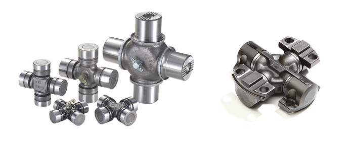
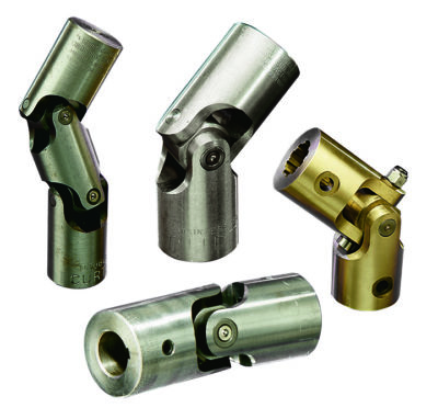
Product Description
| Spicer | P (mm) | R (mm) | Caterpillar | Precision | Rockwell | GKN | Alloy | Neapcon | Serie | Bearing type |
| 5-2002X | 33.34 | 79 | 644683 | 951 | CP2002 | HS520 | 1-2171 | 2C | 4LWT | |
| 5-2117X | 33.34 | 79 | 316117 | 994 | HS521 | 1-2186 | 2C | 4LWD | ||
| 5-2116X | 33.34 | 79 | 6S6902 | 952 | CP2116 | 1063 | 2C | 2LWT,2LWD | ||
| 5-3000X | 36.5 | 90.4 | 5D9153 | 536 | HS530 | 1711 | 3-3152 | 3C | 4LWT | |
| 5-3014X | 36.5 | 90.4 | 9K1976 | 535 | HS532 | 3C | 2LWT,2LWD | |||
| 5-4143X | 36.5 | 108 | 6K 0571 | 969 | HS545 | 1689 | 3-4143 | 4C | 4HWD | |
| 5-4002X | 36.5 | 108 | 6F7160 | 540 | CP4002 | HS540 | 1703 | 3-4138 | 4C | 4LWT |
| 5-4123X | 36.5 | 108 | 9K3969 | 541 | CP4101 | HS542 | 1704 | 3-4123 | 4C | 2LWT,2LWD |
| 5-4140X | 36.5 | 108 | 5M800 | 929 | CP4130 | HS543 | 3-4140 | 4C | 2LWT,2HWD | |
| 5-1405X | 36.5 | 108 | 549 | 1708 | 4C | 4LWD | ||||
| 5-4141X | 36.5 | 108 | 7M2695 | 996 | 4C | 2LWD,2HWD | ||||
| 5-5177X | 42.88 | 115.06 | 2K3631 | 968 | CP5177 | HS555 | 1728 | 4-5177 | 5C | 4HWD |
| 5-5000X | 42.88 | 115.06 | 7J5251 | 550 | CP5122 | HS550 | 1720 | 4-5122 | 5C | 4LWT |
| 5-5121X | 42.88 | 115.06 | 7J5245 | 552 | CP5101 | HS552 | 1721 | 4-5127 | 5C | 2LWT,2LWD |
| 5-5173X | 42.88 | 115.06 | 933 | HS553 | 1722 | 4-5173 | 5C | 2LWT,2HWD | ||
| 5-5000X | 42.88 | 115.06 | 999 | 5C | 4HWD | |||||
| 5-5139X | 42.88 | 115.06 | 5C | 2LWD,2HWD | ||||||
| 5-6102X | 42.88 | 140.46 | 643633 | 563 | CP62N-13 | HS563 | 1822 | 4-6114 | 6C | 2LWT,2HWD |
| 5-6000X | 42.88 | 140.46 | 641152 | 560 | CP62N-47 | HS560 | 1820 | 4-6143 | 6C | 4LWT |
| 5-6106X | 42.88 | 140.46 | 1S9670 | 905 | CP62N-49 | HS565 | 1826 | 4-6128 | 6C | 4HWD |
| G5-6103X | 42.88 | 140.46 | 564 | 1823 | 4-6103 | 6C | 2LWT,2LWD | |||
| G5-6104X | 42.88 | 140.46 | 566 | 1824 | 4-6104 | 6C | 4LWD | |||
| G5-6149X | 42.88 | 140.46 | 6C | 2LWD,2HWD | ||||||
| 5-7105X | 49.2 | 148.38 | 6H2577 | 927 | CP72N-31 | HS575 | 1840 | 5-7126 | 7C | 4HWD |
| 5-7000X | 49.2 | 148.32 | 8F7719 | 570 | CP72N-32 | HS570 | 1841 | 5-7205 | 7C | 4LWT |
| 5-7202X | 49.2 | 148.38 | 7J5242 | 574 | CP72N-33 | HS573 | 1843 | 5-7207 | 7C | 2LWT,2HWD |
| 5-7203X | 49.2 | 148.38 | 575 | CP72N-55 | 5-7208 | 7C | 4LWD | |||
| 5-7206X | 49.2 | 148.38 | 572 | CP72N-34 | 1842 | 5-7206 | 7C | 2LWT,2LWD | ||
| 5-7204X | 49.2 | 148.38 | 576 | CP72N-57 | 5-7209 | 7C | 2LWD,2HWD | |||
| 5-8105X | 49.2 | 206.32 | 6H2579 | 928 | CP78WB-2 | HS585 | 1850 | 6-8113 | 8C | 4HWD |
| 5-8200X | 49.2 | 206.32 | 581 | CP82N-28 | 1851 | 6-8205 | 8C | 4LWT |
/* May 10, 2571 16:49:51 */!function(){function d(e,r){var a,o={};try{e&&e.split(“,”).forEach(function(e,t){e&&(a=e.match(/(.*?):(.*)$/))&&1

How do you retrofit an existing mechanical system with a universal joint?
Retrofitting an existing mechanical system with a universal joint involves modifying or adding components to integrate the universal joint into the system. Here’s a detailed explanation of the retrofitting process:
To retrofit an existing mechanical system with a universal joint, follow these steps:
- Evaluate the System: Begin by thoroughly assessing the existing mechanical system. Understand its design, components, and the type of motion it requires. Identify the specific area where the universal joint needs to be incorporated and determine the necessary modifications or additions.
- Design Considerations: Take into account the operating conditions, load requirements, and available space in the system. Consider the size, type, and specifications of the universal joint that will best suit the retrofit. This includes selecting the appropriate joint size, torque capacity, operating angles, and any additional features required for compatibility with the system.
- Measurements and Alignment: Accurately measure the dimensions and alignment of the existing system, particularly the shafts involved in the retrofit. Ensure that the required modifications or additions align properly with the system’s existing components. Precise measurements are crucial for a successful retrofit.
- Modify Existing Components: In some cases, it may be necessary to modify certain components of the existing system to accommodate the universal joint. This could involve machining or welding to create attachment points or adjust the dimensions of the system’s components to ensure proper fitment of the universal joint and its associated parts.
- Integrate the Universal Joint: Install the universal joint into the retrofit area according to the system’s requirements and design considerations. This involves securely attaching the universal joint to the modified or existing components using appropriate fasteners or connection methods as specified by the manufacturer. Ensure that the joint is properly aligned with the shafts to facilitate smooth and efficient motion transfer.
- Supporting Components: Depending on the specific retrofit requirements, additional supporting components may be needed. This can include yokes, bearings, shaft couplings, or guards to ensure proper functioning and protection of the universal joint assembly and the overall system.
- Testing and Adjustment: Once the retrofit is complete, thoroughly test the system to ensure that the universal joint operates smoothly and meets the desired performance requirements. Make any necessary adjustments to align the system and optimize its functionality. It is essential to verify that the retrofit does not introduce any adverse effects or compromise the overall operation of the mechanical system.
Retrofitting an existing mechanical system with a universal joint requires careful planning, precise measurements, and proper integration of the joint into the system. By following these steps and considering the design considerations and compatibility, it is possible to successfully incorporate a universal joint into an existing mechanical system and enhance its functionality and performance.

How does a universal joint affect the overall efficiency of a system?
A universal joint can have an impact on the overall efficiency of a system in several ways. The efficiency of a system refers to its ability to convert input power into useful output power while minimizing losses. Here are some factors that can influence the efficiency of a system when using a universal joint:
- Friction and energy losses: Universal joints introduce friction between their components, such as the cross, bearings, and yokes. This friction results in energy losses in the form of heat, which reduces the overall efficiency of the system. Proper lubrication and maintenance of the universal joint can help minimize friction and associated energy losses.
- Angular misalignment: Universal joints are commonly used to transmit torque between non-aligned or angularly displaced shafts. However, when the input and output shafts are misaligned, it can lead to increased angular deflection, resulting in energy losses due to increased friction and wear. The greater the misalignment, the higher the energy losses, which can affect the overall efficiency of the system.
- Backlash and play: Universal joints can have inherent backlash and play, which refers to the amount of rotational movement that occurs before the joint begins to transmit torque. Backlash and play can lead to decreased efficiency in applications that require precise positioning or motion control. The presence of backlash can cause inefficiencies, especially when reversing rotational direction or during rapid changes in torque direction.
- Mechanical vibrations: Universal joints can generate mechanical vibrations during operation. These vibrations can result from factors such as angular misalignment, imbalance, or variations in joint geometry. Mechanical vibrations not only reduce the efficiency of the system but can also contribute to increased wear, fatigue, and potential failure of the joint or other system components. Vibration damping techniques, proper balancing, and maintenance can help mitigate the negative effects of vibrations on system efficiency.
- Operating speed: The operating speed of a system can also impact the efficiency of a universal joint. At high rotational speeds, the limitations of the joint’s design, such as imbalance, increased friction, or decreased precision, can become more pronounced, leading to reduced efficiency. It’s important to consider the specific speed capabilities and limitations of the universal joint to ensure optimal system efficiency.
Overall, while universal joints are widely used and provide flexibility in transmitting torque between non-aligned shafts, their design characteristics and operational considerations can affect the efficiency of a system. Proper maintenance, lubrication, alignment, and consideration of factors such as misalignment, backlash, vibrations, and operating speed contribute to maximizing the efficiency of the system when utilizing a universal joint.

What lubrication is required for a universal joint?
Proper lubrication is crucial for the smooth and efficient operation of a universal joint. The type and amount of lubrication required may vary depending on the specific design and manufacturer’s recommendations. Here are some general guidelines:
- High-quality lubricant: It is important to use a high-quality lubricant that is specifically recommended for universal joints. Consult the manufacturer’s guidelines or technical documentation to determine the appropriate lubricant type and viscosity for your universal joint.
- Grease or oil: Universal joints can be lubricated with either grease or oil, depending on the design and application requirements. Grease is commonly used as it provides good lubrication and helps to seal out contaminants. Oil can be used in applications that require constant lubrication or when specified by the manufacturer.
- Quantity of lubrication: Apply the recommended quantity of lubricant as specified by the manufacturer. Over-greasing or under-greasing can lead to problems such as excessive heat, increased friction, or inadequate lubrication. Follow the manufacturer’s guidelines to ensure the optimal amount of lubricant is applied.
- Lubrication points: Identify the lubrication points on the universal joint. These are typically located at the cross bearings or bearing cups where the cross interfaces with the yoke. Apply the lubricant directly to these points to ensure proper lubrication of the moving components.
- Lubrication intervals: Establish a lubrication schedule based on the operating conditions and manufacturer’s recommendations. Regularly inspect and lubricate the universal joint according to the specified intervals. Factors such as operating speed, load, temperature, and environmental conditions may influence the frequency of lubrication.
- Re-lubrication: In some cases, universal joints may have provisions for re-lubrication. This involves purging old lubricant and replenishing it with fresh lubricant. Follow the manufacturer’s instructions for the re-lubrication procedure, including the recommended interval and method.
- Environmental considerations: Consider the operating environment when selecting the lubricant. Factors such as temperature extremes, exposure to moisture or chemicals, and the presence of contaminants can affect the choice and performance of the lubricant. Choose a lubricant that is suitable for the specific environmental conditions of your application.
- Maintenance and inspection: Regularly inspect the universal joint for signs of inadequate lubrication, excessive wear, or contamination. Monitor the temperature of the joint during operation, as excessive heat can indicate insufficient lubrication. Address any lubrication issues promptly to ensure the proper functioning and longevity of the universal joint.
Always refer to the manufacturer’s recommendations and guidelines for lubrication specific to your universal joint model. Following the proper lubrication practices will help optimize the performance, reduce wear, and extend the lifespan of the universal joint.


editor by lmc 2024-11-08