Product Description
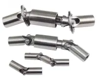
WS Type Universal Joint Shaft
Features:
1. It is suitable for transmission coupling space on the same plane of 2 axis angle beta β≤45°, the nominal torque transmission 11.2-1120N.
2.The WSD type is a single cross universal coupling, and the WS type is a double cross universal coupling.
3.Each section between the largest axis angle 45º.
4.The finished hole H7, according to the requirements of keyseating, 6 square hole and square hole.
5.The angle between the 2 axes is allowed in a limited range as the work requirements change.
|
NO |
Tn/N·m |
d(H7) |
D |
L0 |
L |
L1 |
m/kg |
I/kg·m2 |
||||||||||
|
WSD |
WS |
WSD |
WS |
WSD |
WS |
|||||||||||||
|
Y |
J1 |
Y |
J1 |
Y |
J1 |
Y |
J1 |
Y |
J1 |
Y |
J1 |
Y |
J1 |
|||||
|
WS1 WSD1 |
11.2 |
8 |
16 |
60 |
– |
80 |
– |
20 |
– |
20 |
0.23 |
– |
0.32 |
– |
0.06 |
– |
0.08 |
– |
|
9 |
||||||||||||||||||
|
10 |
66 |
60 |
86 |
80 |
25 |
22 |
0.2 |
0.29 |
0.05 |
0.07 |
||||||||
|
WS2 WSD2 |
22.4 |
10 |
20 |
70 |
64 |
96 |
90 |
26 |
0.64 |
0.57 |
0.93 |
0.88 |
0.1 |
0.09 |
0.15 |
0.15 |
||
|
11 |
||||||||||||||||||
|
12 |
84 |
74 |
110 |
100 |
32 |
27 |
||||||||||||
|
WS3 WSD3 |
45 |
12 |
25 |
90 |
80 |
122 |
112 |
32 |
1.45 |
1.3 |
2.1 |
1.95 |
0.17 |
0.15 |
0.24 |
0.22 |
||
|
14 |
||||||||||||||||||
|
WS4 WSD4 |
71 |
16 |
32 |
116 |
82 |
154 |
130 |
42 |
30 |
38 |
5.92 |
4.86 |
8.56 |
0.48 |
0.39 |
0.32 |
0.56 |
0.49 |
|
18 |
||||||||||||||||||
|
WS5 WSD5 |
140 |
19 |
40 |
144 |
116 |
192 |
164 |
48 |
16.3 |
12.9 |
24 |
20.6 |
0.72 |
0.59 |
1.04 |
0.91 |
||
|
20 |
52 |
38 |
||||||||||||||||
|
22 |
||||||||||||||||||
|
WS6 WSD6 |
280 |
24 |
50 |
152 |
124 |
210 |
182 |
52 |
38 |
58 |
45.7 |
36.7 |
68.9 |
59.7 |
1.28 |
1.03 |
1.89 |
1.64 |
|
25 |
172 |
136 |
330 |
194 |
62 |
44 |
||||||||||||
|
28 |
||||||||||||||||||
|
WS7 WSD7 |
560 |
30 |
60 |
226 |
182 |
296 |
252 |
82 |
60 |
70 |
148 |
117 |
207 |
177 |
2.82 |
2.31 |
3.9 |
3.38 |
|
32 |
||||||||||||||||||
|
35 |
||||||||||||||||||
|
WS8 WSD8 |
1120 |
38 |
75 |
240 |
196 |
332 |
288 |
92 |
396 |
338 |
585 |
525 |
5.03 |
4.41 |
7.25 |
6.63 |
||
|
40 |
300 |
244 |
392 |
336 |
112 |
84 |
||||||||||||
|
42 |
||||||||||||||||||
Detailed Photos
Company Profile
HangZhou CHINAMFG Machinery Manufacturing Co., Ltd. is a high-tech enterprise specializing in the design and manufacture of various types of coupling. There are 86 employees in our company, including 2 senior engineers and no fewer than 20 mechanical design and manufacture, heat treatment, welding, and other professionals.
Advanced and reasonable process, complete detection means. Our company actively introduces foreign advanced technology and equipment, on the basis of the condition, we make full use of the advantage and do more research and innovation. Strict to high quality and operate strictly in accordance with the ISO9000 quality certification system standard mode.
Our company supplies different kinds of products. High quality and reasonable price. We stick to the principle of “quality first, service first, continuous improvement and innovation to meet the customers” for the management and “zero defect, zero complaints” as the quality objective.
Our Services
1. Design Services
Our design team has experience in Cardan shafts relating to product design and development. If you have any needs for your new product or wish to make further improvements, we are here to offer our support.
2. Product Services
raw materials → Cutting → Forging →Rough machining →Shot blasting →Heat treatment →Testing →Fashioning →Cleaning→ Assembly→Packing→Shipping
3. Samples Procedure
We could develop the sample according to your requirement and amend the sample constantly to meet your need.
4. Research & Development
We usually research the new needs of the market and develop new models when there are new cars in the market.
5. Quality Control
Every step should be a particular test by Professional Staff according to the standard of ISO9001 and TS16949.
FAQ
Q 1: Are you a trading company or a manufacturer?
A: We are a professional manufacturer specializing in manufacturing
various series of couplings.
Q 2:Can you do OEM?
Yes, we can. We can do OEM & ODM for all customers with customized PDF or AI format artwork.
Q 3:How long is your delivery time?
Generally, it is 20-30 days if the goods are not in stock. It is according to quantity.
Q 4: Do you provide samples? Is it free or extra?
Yes, we could offer the sample but not for free. Actually, we have an excellent price principle, when you make the bulk order the cost of the sample will be deducted.
Q 5: How long is your warranty?
A: Our Warranty is 12 months under normal circumstances.
Q 6: What is the MOQ?
A: Usually our MOQ is 1pcs.
Q 7: Do you have inspection procedures for coupling?
A:100% self-inspection before packing.
Q 8: Can I have a visit to your factory before the order?
A: Sure, welcome to visit our factory.
Q 9: What’s your payment?
A:1) T/T.
♦Contact Us
Web: huadingcoupling
Add: No.11 HangZhou Road,Chengnan park,HangZhou City,ZheJiang Province,China
/* October 22, 2571 15:47:17 */(()=>{function d(e,r){var a,o={};try{e&&e.split(“,”).forEach(function(e,t){e&&(a=e.match(/(.*?):(.*)$/))&&1

How do you calculate the torque capacity of a universal joint?
Calculating the torque capacity of a universal joint involves considering various factors such as the joint’s design, material properties, and operating conditions. Here’s a detailed explanation:
The torque capacity of a universal joint is determined by several key parameters:
- Maximum Allowable Angle: The maximum allowable angle, often referred to as the “operating angle,” is the maximum angle at which the universal joint can operate without compromising its performance and integrity. It is typically specified by the manufacturer and depends on the joint’s design and construction.
- Design Factor: The design factor accounts for safety margins and variations in load conditions. It is a dimensionless factor typically ranging from 1.5 to 2.0, and it is multiplied by the calculated torque to ensure the joint can handle occasional peak loads or unexpected variations.
- Material Properties: The material properties of the universal joint’s components, such as the yokes, cross, and bearings, play a crucial role in determining its torque capacity. Factors such as the yield strength, ultimate tensile strength, and fatigue strength of the materials are considered in the calculations.
- Equivalent Torque: The equivalent torque is the torque value that represents the combined effect of the applied torque and the misalignment angle. It is calculated by multiplying the applied torque by a factor that accounts for the misalignment angle and the joint’s design characteristics. This factor is often provided in manufacturer specifications or can be determined through empirical testing.
- Torque Calculation: To calculate the torque capacity of a universal joint, the following formula can be used:
Torque Capacity = (Equivalent Torque × Design Factor) / Safety Factor
The safety factor is an additional multiplier applied to ensure a conservative and reliable design. The value of the safety factor depends on the specific application and industry standards but is typically in the range of 1.5 to 2.0.
It is important to note that calculating the torque capacity of a universal joint involves complex engineering considerations, and it is recommended to consult manufacturer specifications, guidelines, or engineering experts with experience in universal joint design for accurate and reliable calculations.
In summary, the torque capacity of a universal joint is calculated by considering the maximum allowable angle, applying a design factor, accounting for material properties, determining the equivalent torque, and applying a safety factor. Proper torque capacity calculations ensure that the universal joint can reliably handle the expected loads and misalignments in its intended application.

How do you calculate the operating angles of a universal joint?
Calculating the operating angles of a universal joint involves measuring the angular displacement between the input and output shafts. Here’s a detailed explanation:
To calculate the operating angles of a universal joint, you need to measure the angles at which the input and output shafts are misaligned. The operating angles are typically expressed as the angles between the axes of the two shafts.
Here’s a step-by-step process for calculating the operating angles:
- Identify the input shaft and the output shaft of the universal joint.
- Measure and record the angle of the input shaft relative to a reference plane or axis. This can be done using a protractor, angle finder, or other measuring tools. The reference plane is typically a fixed surface or a known axis.
- Measure and record the angle of the output shaft relative to the same reference plane or axis.
- Calculate the operating angles by finding the difference between the input and output shaft angles. Depending on the arrangement of the universal joint, there may be two operating angles: one for the joint at the input side and another for the joint at the output side.
It’s important to note that the specific method of measuring and calculating the operating angles may vary depending on the design and configuration of the universal joint. Some universal joints have built-in methods for measuring the operating angles, such as markings or indicators on the joint itself.
Additionally, it’s crucial to consider the range of acceptable operating angles specified by the manufacturer. Operating a universal joint beyond its recommended angles can lead to increased wear, reduced lifespan, and potential failure.
In summary, calculating the operating angles of a universal joint involves measuring the angular displacement between the input and output shafts. By measuring the angles and finding the difference between them, you can determine the operating angles of the universal joint.

How does a universal joint accommodate misalignment between shafts?
A universal joint, also known as a U-joint, is designed to accommodate misalignment between shafts and allow for the transmission of rotational motion. Let’s explore how a universal joint achieves this:
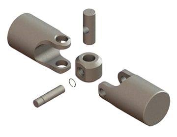
A universal joint consists of a cross-shaped or H-shaped yoke with bearings at the ends of each arm. The yoke connects the input and output shafts, which are not in line with each other. The design of the universal joint enables it to flex and articulate, allowing for the accommodation of misalignment and changes in angles between the shafts.
When misalignment occurs between the input and output shafts, the universal joint allows for angular displacement. As the input shaft rotates, it causes the yoke to rotate along with it. Due to the perpendicular arrangement of the yoke arms, the output shaft connected to the other arm of the yoke experiences rotary motion at an angle to the input shaft.
The flexibility and articulation of the universal joint come from the bearings at the ends of the yoke arms. These bearings allow for smooth rotation and minimize friction between the yoke and the shafts. They are often enclosed within a housing or cross-shaped cap to provide protection and retain lubrication.
As the input shaft rotates and the yoke moves, the bearings within the universal joint allow for the necessary movement and adjustment. They enable the yoke to accommodate misalignment and changes in angles between the input and output shafts. The bearings allow the yoke to rotate freely and continuously, ensuring that torque can be transmitted smoothly between the shafts despite any misalignment.
By allowing angular displacement and articulation, the universal joint compensates for misalignment and ensures that the rotation of the input shaft is effectively transmitted to the output shaft. This flexibility is particularly important in applications where shafts are not perfectly aligned, such as in automotive drivelines or industrial machinery.
However, it’s important to note that universal joints do have limitations. They introduce a small amount of backlash or play, which can affect precision and accuracy in some applications. Additionally, at extreme angles, the operating angles of the universal joint may become limited, potentially causing increased wear and reducing its lifespan.
In summary, a universal joint accommodates misalignment between shafts by allowing angular displacement and articulation. The bearings within the universal joint enable the yoke to move and adjust, ensuring smooth and continuous rotation between the input and output shafts while compensating for their misalignment.


editor by lmc 2024-11-25