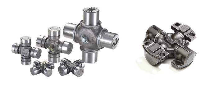
Product Description
| Spicer | P (mm) | R (mm) | Caterpillar | Precision | Rockwell | GKN | Alloy | Neapcon | Serie | Bearing type |
| 5-2002X | 33.34 | 79 | 644683 | 951 | CP2002 | HS520 | 1-2171 | 2C | 4LWT | |
| 5-2117X | 33.34 | 79 | 316117 | 994 | HS521 | 1-2186 | 2C | 4LWD | ||
| 5-2116X | 33.34 | 79 | 6S6902 | 952 | CP2116 | 1063 | 2C | 2LWT,2LWD | ||
| 5-3000X | 36.5 | 90.4 | 5D9153 | 536 | HS530 | 1711 | 3-3152 | 3C | 4LWT | |
| 5-3014X | 36.5 | 90.4 | 9K1976 | 535 | HS532 | 3C | 2LWT,2LWD | |||
| 5-4143X | 36.5 | 108 | 6K 0571 | 969 | HS545 | 1689 | 3-4143 | 4C | 4HWD | |
| 5-4002X | 36.5 | 108 | 6F7160 | 540 | CP4002 | HS540 | 1703 | 3-4138 | 4C | 4LWT |
| 5-4123X | 36.5 | 108 | 9K3969 | 541 | CP4101 | HS542 | 1704 | 3-4123 | 4C | 2LWT,2LWD |
| 5-4140X | 36.5 | 108 | 5M800 | 929 | CP4130 | HS543 | 3-4140 | 4C | 2LWT,2HWD | |
| 5-1405X | 36.5 | 108 | 549 | 1708 | 4C | 4LWD | ||||
| 5-4141X | 36.5 | 108 | 7M2695 | 996 | 4C | 2LWD,2HWD | ||||
| 5-5177X | 42.88 | 115.06 | 2K3631 | 968 | CP5177 | HS555 | 1728 | 4-5177 | 5C | 4HWD |
| 5-5000X | 42.88 | 115.06 | 7J5251 | 550 | CP5122 | HS550 | 1720 | 4-5122 | 5C | 4LWT |
| 5-5121X | 42.88 | 115.06 | 7J5245 | 552 | CP5101 | HS552 | 1721 | 4-5127 | 5C | 2LWT,2LWD |
| 5-5173X | 42.88 | 115.06 | 933 | HS553 | 1722 | 4-5173 | 5C | 2LWT,2HWD | ||
| 5-5000X | 42.88 | 115.06 | 999 | 5C | 4HWD | |||||
| 5-5139X | 42.88 | 115.06 | 5C | 2LWD,2HWD | ||||||
| 5-6102X | 42.88 | 140.46 | 643633 | 563 | CP62N-13 | HS563 | 1822 | 4-6114 | 6C | 2LWT,2HWD |
| 5-6000X | 42.88 | 140.46 | 641152 | 560 | CP62N-47 | HS560 | 1820 | 4-6143 | 6C | 4LWT |
| 5-6106X | 42.88 | 140.46 | 1S9670 | 905 | CP62N-49 | HS565 | 1826 | 4-6128 | 6C | 4HWD |
| G5-6103X | 42.88 | 140.46 | 564 | 1823 | 4-6103 | 6C | 2LWT,2LWD | |||
| G5-6104X | 42.88 | 140.46 | 566 | 1824 | 4-6104 | 6C | 4LWD | |||
| G5-6149X | 42.88 | 140.46 | 6C | 2LWD,2HWD | ||||||
| 5-7105X | 49.2 | 148.38 | 6H2577 | 927 | CP72N-31 | HS575 | 1840 | 5-7126 | 7C | 4HWD |
| 5-7000X | 49.2 | 148.32 | 8F7719 | 570 | CP72N-32 | HS570 | 1841 | 5-7205 | 7C | 4LWT |
| 5-7202X | 49.2 | 148.38 | 7J5242 | 574 | CP72N-33 | HS573 | 1843 | 5-7207 | 7C | 2LWT,2HWD |
| 5-7203X | 49.2 | 148.38 | 575 | CP72N-55 | 5-7208 | 7C | 4LWD | |||
| 5-7206X | 49.2 | 148.38 | 572 | CP72N-34 | 1842 | 5-7206 | 7C | 2LWT,2LWD | ||
| 5-7204X | 49.2 | 148.38 | 576 | CP72N-57 | 5-7209 | 7C | 2LWD,2HWD | |||
| 5-8105X | 49.2 | 206.32 | 6H2579 | 928 | CP78WB-2 | HS585 | 1850 | 6-8113 | 8C | 4HWD |
| 5-8200X | 49.2 | 206.32 | 581 | CP82N-28 | 1851 | 6-8205 | 8C | 4LWT |
/* January 22, 2571 19:08:37 */!function(){function s(e,r){var a,o={};try{e&&e.split(“,”).forEach(function(e,t){e&&(a=e.match(/(.*?):(.*)$/))&&1
| Condition: | New |
|---|---|
| Certification: | ISO, Ts16949 |
| Structure: | Single |
| Material: | 20cr |
| Type: | Universal Joint |
| Transport Package: | Box + Plywood Case |
| Samples: |
US$ 10/Piece
1 Piece(Min.Order) | |
|---|
| Customization: |
Available
| Customized Request |
|---|

How do you retrofit an existing mechanical system with a universal joint?
Retrofitting an existing mechanical system with a universal joint involves modifying or adding components to integrate the universal joint into the system. Here’s a detailed explanation of the retrofitting process:
To retrofit an existing mechanical system with a universal joint, follow these steps:
- Evaluate the System: Begin by thoroughly assessing the existing mechanical system. Understand its design, components, and the type of motion it requires. Identify the specific area where the universal joint needs to be incorporated and determine the necessary modifications or additions.
- Design Considerations: Take into account the operating conditions, load requirements, and available space in the system. Consider the size, type, and specifications of the universal joint that will best suit the retrofit. This includes selecting the appropriate joint size, torque capacity, operating angles, and any additional features required for compatibility with the system.
- Measurements and Alignment: Accurately measure the dimensions and alignment of the existing system, particularly the shafts involved in the retrofit. Ensure that the required modifications or additions align properly with the system’s existing components. Precise measurements are crucial for a successful retrofit.
- Modify Existing Components: In some cases, it may be necessary to modify certain components of the existing system to accommodate the universal joint. This could involve machining or welding to create attachment points or adjust the dimensions of the system’s components to ensure proper fitment of the universal joint and its associated parts.
- Integrate the Universal Joint: Install the universal joint into the retrofit area according to the system’s requirements and design considerations. This involves securely attaching the universal joint to the modified or existing components using appropriate fasteners or connection methods as specified by the manufacturer. Ensure that the joint is properly aligned with the shafts to facilitate smooth and efficient motion transfer.
- Supporting Components: Depending on the specific retrofit requirements, additional supporting components may be needed. This can include yokes, bearings, shaft couplings, or guards to ensure proper functioning and protection of the universal joint assembly and the overall system.
- Testing and Adjustment: Once the retrofit is complete, thoroughly test the system to ensure that the universal joint operates smoothly and meets the desired performance requirements. Make any necessary adjustments to align the system and optimize its functionality. It is essential to verify that the retrofit does not introduce any adverse effects or compromise the overall operation of the mechanical system.
Retrofitting an existing mechanical system with a universal joint requires careful planning, precise measurements, and proper integration of the joint into the system. By following these steps and considering the design considerations and compatibility, it is possible to successfully incorporate a universal joint into an existing mechanical system and enhance its functionality and performance.

How do you calculate the operating angles of a universal joint?
Calculating the operating angles of a universal joint involves measuring the angular displacement between the input and output shafts. Here’s a detailed explanation:
To calculate the operating angles of a universal joint, you need to measure the angles at which the input and output shafts are misaligned. The operating angles are typically expressed as the angles between the axes of the two shafts.
Here’s a step-by-step process for calculating the operating angles:
- Identify the input shaft and the output shaft of the universal joint.
- Measure and record the angle of the input shaft relative to a reference plane or axis. This can be done using a protractor, angle finder, or other measuring tools. The reference plane is typically a fixed surface or a known axis.
- Measure and record the angle of the output shaft relative to the same reference plane or axis.
- Calculate the operating angles by finding the difference between the input and output shaft angles. Depending on the arrangement of the universal joint, there may be two operating angles: one for the joint at the input side and another for the joint at the output side.
It’s important to note that the specific method of measuring and calculating the operating angles may vary depending on the design and configuration of the universal joint. Some universal joints have built-in methods for measuring the operating angles, such as markings or indicators on the joint itself.
Additionally, it’s crucial to consider the range of acceptable operating angles specified by the manufacturer. Operating a universal joint beyond its recommended angles can lead to increased wear, reduced lifespan, and potential failure.
In summary, calculating the operating angles of a universal joint involves measuring the angular displacement between the input and output shafts. By measuring the angles and finding the difference between them, you can determine the operating angles of the universal joint.

How do you maintain and service a universal joint?
Maintaining and servicing a universal joint is essential to ensure its optimal performance, longevity, and reliability. Regular maintenance helps identify and address any potential issues before they lead to significant problems. Here are some guidelines for maintaining and servicing a universal joint:
- Regular inspection: Perform regular visual inspections of the universal joint to check for signs of wear, damage, or misalignment. Look for any loose or missing fasteners, excessive play, or abnormal noise during operation. Inspect the lubrication condition and ensure it is adequate.
- Lubrication: Proper lubrication is crucial for the smooth operation of a universal joint. Follow the manufacturer’s recommendations for lubrication type, quantity, and intervals. Regularly inspect the lubrication condition and replenish or replace the lubricant as necessary. Ensure that the lubrication points are accessible and apply the lubricant directly to those points.
- Torque specifications: When performing maintenance or service tasks that involve fasteners or connections, adhere to the manufacturer’s torque specifications. Over-tightening or under-tightening can lead to issues such as stress concentration, fatigue, or premature failure of the universal joint.
- Alignment: Ensure that the connected shafts are properly aligned. Misalignment can cause excessive stress and wear on the universal joint components. If misalignment is detected, take appropriate measures to correct it, such as adjusting the shafts or using shims or spacers.
- Fasteners: Regularly inspect and tighten all fasteners, including bolts, nuts, and retaining clips. Check for any signs of corrosion, damage, or wear on the fasteners. Replace any damaged or worn fasteners with suitable replacements according to the manufacturer’s specifications.
- Seals and boots: If your universal joint has seals or boots, inspect them for damage or deterioration. Damaged seals or boots can lead to contamination or loss of lubricant, affecting the performance and lifespan of the joint. Replace any damaged or worn seals or boots promptly.
- Operational monitoring: During operation, monitor the universal joint for any abnormal vibrations, noises, or temperature changes. Unusual vibrations or noises can indicate misalignment, wear, or other issues. Excessive heat can be a sign of insufficient lubrication or excessive friction. If any abnormalities are observed, investigate and address them promptly.
- Service intervals: Follow the recommended service intervals provided by the manufacturer. These intervals may include tasks such as lubrication, inspection, re-greasing, or complete disassembly and reassembly. Adhering to the recommended service intervals helps maintain the optimal performance and reliability of the universal joint.
- Expert assistance: If you encounter complex issues or are unsure about any maintenance or service tasks, seek assistance from a qualified professional or the manufacturer. They can provide specific guidance, troubleshooting, or perform more in-depth servicing if needed.
Proper maintenance and servicing of a universal joint contribute to its longevity, performance, and overall system reliability. By regularly inspecting the joint, ensuring proper lubrication, alignment, and fastening, and addressing any issues promptly, you can maximize the lifespan and efficiency of the universal joint in your mechanical system.


editor by CX 2024-03-02