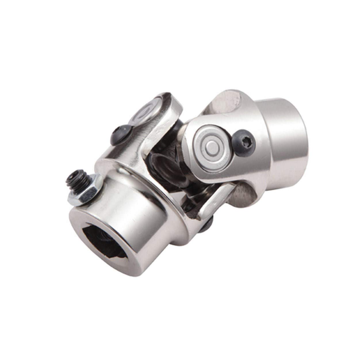
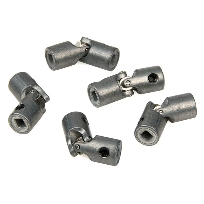
Product Description
HangZhou Hua Xihu (West Lake) Dis. Auto Parts Co., Ltd is located in the beautiful HangZhou, China. The transportation is very covenient as it closed to CHINAMFG international air port and ZheJiang , and HangZhou freeway in the CHINAMFG area of the yangtze River Delta.
Our company is a monern enterprise that combines development disign, manufacturer, sale and service, and it’s products including to :
Drive shaft, weld yoke, Flange yoke, spline yoke, slip joints, spline shafts, sleeve tube
Cardan shafts,
PTO Shaft, pin yoke, inner yoke, outer yoke,
Off-Highway Cardan Shafts,
Universal joints, Cross, U-Joints.
MECHANICS Universal joints, CHINAMFG style u-joints,
Tractor spare parts, MTZ spare parts.
/* March 10, 2571 17:59:20 */!function(){function s(e,r){var a,o={};try{e&&e.split(“,”).forEach(function(e,t){e&&(a=e.match(/(.*?):(.*)$/))&&1
| Material: | Alloy |
|---|---|
| Type: | Universal Joint |
| Certification: | ISO |
| Automatic: | Automatic |
| Condition: | New |
| Transport Package: | Export Packing |
| Customization: |
Available
| Customized Request |
|---|

How do you ensure proper alignment when connecting a universal joint?
Ensuring proper alignment when connecting a universal joint is essential for its optimal performance and longevity. Here’s a detailed explanation:
Proper alignment of a universal joint involves aligning the input and output shafts to minimize angular misalignment and maintain a smooth and efficient power transfer. Here are the steps to ensure proper alignment:
- Measure shaft angles: Begin by measuring the angles of the input and output shafts that the universal joint will connect. This can be done using a protractor or an angle measuring tool. The angles should be measured in relation to a common reference plane, such as the horizontal or vertical.
- Calculate the operating angle: The operating angle of the universal joint is the difference between the angles of the input and output shafts. This angle determines the amount of angular misalignment that the universal joint needs to accommodate. It is crucial to calculate the operating angle accurately to ensure the proper selection of a universal joint suitable for the application.
- Select the appropriate universal joint: Based on the calculated operating angle, choose a universal joint that is designed to handle the specific misalignment requirements. Universal joints come in various sizes and designs to accommodate different operating angles and torque loads. Refer to the manufacturer’s specifications and guidelines to select the appropriate universal joint for the application.
- Achieve parallel alignment: To ensure proper alignment, it is important to align the input and output shafts so that they are parallel to each other when viewed from the common reference plane. This can be achieved by adjusting the mounting positions of the shafts or using alignment tools such as straightedges or laser alignment systems. The goal is to minimize any offset or skew between the shafts.
- Check centerline alignment: Once the shafts are parallel, it is necessary to check the centerline alignment. This involves verifying that the centerline of the input shaft and the centerline of the output shaft are in line with each other. Misalignment in the centerline can result in additional stress on the universal joint and lead to premature wear or failure. Use measurement tools or visual inspection to ensure the centerline alignment is maintained.
- Securely fasten the universal joint: After achieving proper alignment, securely fasten the universal joint to the input and output shafts according to the manufacturer’s recommendations. Follow the specified torque values for the fasteners to ensure proper clamping force without over-tightening. This will help maintain the alignment during operation.
- Perform regular maintenance: To ensure continued proper alignment, it is important to perform regular maintenance, including periodic inspections and lubrication of the universal joint. Regular maintenance can help detect any misalignment or wear issues early on and prevent further damage or failure.
By following these steps and paying attention to proper alignment, the universal joint can operate smoothly and effectively, minimizing stress, wear, and the risk of premature failure.
In summary, ensuring proper alignment when connecting a universal joint involves measuring shaft angles, calculating the operating angle, selecting the appropriate universal joint, achieving parallel alignment, checking centerline alignment, securely fastening the joint, and performing regular maintenance.

What is the effect of varying operating angles on the performance of a universal joint?
Varying operating angles can have a significant effect on the performance of a universal joint. Here’s a detailed explanation:
A universal joint is designed to transmit rotational motion between two shafts that are not collinear or have a constant angular relationship. The operating angle refers to the angle between the input and output shafts of the joint. The effects of varying operating angles on the performance of a universal joint are as follows:
- Changes in Torque and Speed: As the operating angle of a universal joint increases or decreases, the torque and speed transmitted through the joint can be affected. At small operating angles, the torque and speed transmission are relatively efficient. However, as the operating angle increases, the torque and speed capacity of the joint may decrease. This reduction in torque and speed capability is due to increased non-uniform loading and bending moments on the joint’s components.
- Increased Vibrations and Noise: Varying operating angles can introduce vibrations and noise in a universal joint. As the operating angle becomes more extreme, the joint experiences higher levels of dynamic imbalance and misalignment. This imbalance can lead to increased vibration levels, which may affect the overall performance and lifespan of the joint. Additionally, the non-uniform motion and increased stress on the joint’s components can generate additional noise during operation.
- Angular Misalignment Compensation: One of the primary advantages of universal joints is their ability to compensate for angular misalignment between shafts. By accommodating varying operating angles, the joint allows for flexibility in transmitting motion even when the input and output shafts are not perfectly aligned. However, extreme operating angles may challenge the joint’s ability to compensate for misalignment effectively. Very large operating angles can lead to increased wear, decreased joint life, and potential loss of motion transmission efficiency.
- Increased Wear and Fatigue: Varying operating angles can contribute to increased wear and fatigue on the universal joint’s components. As the operating angle increases, the joint experiences higher levels of stress and non-uniform loading. This stress concentration can lead to accelerated wear and fatigue, especially at critical areas such as the bearing caps and needle bearings. Continuous operation at extreme operating angles without proper lubrication and maintenance can significantly reduce the joint’s lifespan.
- Heat Generation: Extreme operating angles can result in increased heat generation within the universal joint. The non-uniform motion and increased friction caused by high operating angles can lead to elevated temperatures. Excessive heat can accelerate lubricant breakdown, increase wear rates, and potentially cause premature failure of the joint. Adequate cooling and proper lubrication are essential to mitigate the effects of heat generation in such cases.
- Efficiency and Power Loss: Varying operating angles can impact the overall efficiency of a universal joint. At small to moderate operating angles, the joint can transmit motion with relatively high efficiency. However, as the operating angle increases, the joint’s efficiency may decrease due to increased friction, bending moments, and non-uniform loading. This reduction in efficiency can result in power loss and decreased overall system performance.
Therefore, it is crucial to consider the effects of varying operating angles on the performance of a universal joint. Proper design, careful selection of operating angles within the joint’s specified limits, regular maintenance, and adherence to manufacturer guidelines can help mitigate the potential negative effects and ensure optimal performance and longevity of the joint.

What is a universal joint and how does it work?
A universal joint, also known as a U-joint, is a mechanical coupling that allows for the transmission of rotary motion between two shafts that are not in line with each other. It is commonly used in applications where shafts need to transmit motion at angles or around obstacles. The universal joint consists of a cross-shaped or H-shaped yoke with bearings at the ends of each arm. Let’s explore how it works:
A universal joint typically comprises four main components:
- Input Shaft: The input shaft is the shaft that provides the initial rotary motion.
- Output Shaft: The output shaft is the shaft that receives the rotary motion from the input shaft.
- Yoke: The yoke is a cross-shaped or H-shaped component that connects the input and output shafts. It consists of two arms perpendicular to each other.
- Bearings: Bearings are located at the ends of each arm of the yoke. These bearings allow for smooth rotation and reduce friction between the yoke and the shafts.
When the input shaft rotates, it causes the yoke to rotate along with it. Due to the perpendicular arrangement of the arms, the output shaft connected to the other arm of the yoke experiences rotary motion at an angle to the input shaft.
The universal joint works by accommodating the misalignment between the input and output shafts. As the input shaft rotates, the yoke allows the output shaft to rotate freely and continuously despite any angular displacement or misalignment between the two shafts. This flexibility of the universal joint enables torque to be transmitted smoothly between the shafts while compensating for their misalignment.
During operation, the bearings at the ends of the yoke arms allow for the rotation of the yoke and the connected shafts. The bearings are often enclosed within a housing or cross-shaped cap to provide protection and retain lubrication. The design of the bearings allows for a range of motion and flexibility, allowing the yoke to move and adjust as the shafts rotate at different angles.
The universal joint is commonly used in various applications, including automotive drivelines, industrial machinery, and power transmission systems. It allows for the transmission of rotary motion at different angles and helps compensate for misalignment, eliminating the need for perfectly aligned shafts.
It is important to note that universal joints have certain limitations. They introduce a small amount of backlash or play, which can affect precision and accuracy in some applications. Furthermore, at extreme angles, the operating angles of the universal joint may become limited, potentially causing increased wear and reducing its lifespan.
Overall, the universal joint is a versatile mechanical coupling that enables the transmission of rotary motion between misaligned shafts. Its ability to accommodate angular displacement and misalignment makes it a valuable component in numerous mechanical systems.


editor by CX 2024-02-06