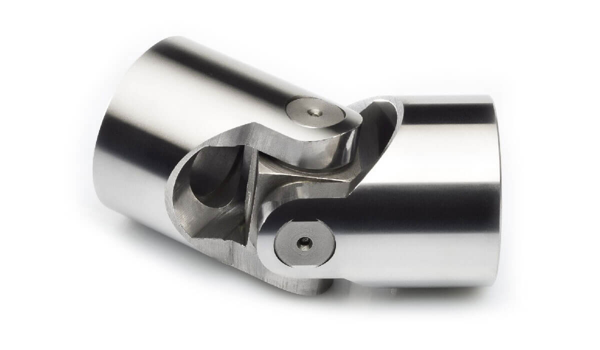
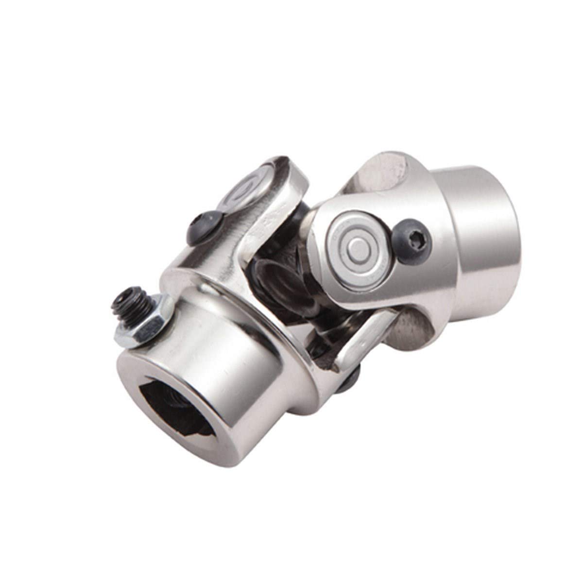
Product Description
| Spicer | P (mm) | R (mm) | Caterpillar | Precision | Rockwell | GKN | Alloy | Neapcon | Serie | Bearing type |
| 5-2002X | 33.34 | 79 | 644683 | 951 | CP2002 | HS520 | 1-2171 | 2C | 4LWT | |
| 5-2117X | 33.34 | 79 | 316117 | 994 | HS521 | 1-2186 | 2C | 4LWD | ||
| 5-2116X | 33.34 | 79 | 6S6902 | 952 | CP2116 | 1063 | 2C | 2LWT,2LWD | ||
| 5-3000X | 36.5 | 90.4 | 5D9153 | 536 | HS530 | 1711 | 3-3152 | 3C | 4LWT | |
| 5-3014X | 36.5 | 90.4 | 9K1976 | 535 | HS532 | 3C | 2LWT,2LWD | |||
| 5-4143X | 36.5 | 108 | 6K 0571 | 969 | HS545 | 1689 | 3-4143 | 4C | 4HWD | |
| 5-4002X | 36.5 | 108 | 6F7160 | 540 | CP4002 | HS540 | 1703 | 3-4138 | 4C | 4LWT |
| 5-4123X | 36.5 | 108 | 9K3969 | 541 | CP4101 | HS542 | 1704 | 3-4123 | 4C | 2LWT,2LWD |
| 5-4140X | 36.5 | 108 | 5M800 | 929 | CP4130 | HS543 | 3-4140 | 4C | 2LWT,2HWD | |
| 5-1405X | 36.5 | 108 | 549 | 1708 | 4C | 4LWD | ||||
| 5-4141X | 36.5 | 108 | 7M2695 | 996 | 4C | 2LWD,2HWD | ||||
| 5-5177X | 42.88 | 115.06 | 2K3631 | 968 | CP5177 | HS555 | 1728 | 4-5177 | 5C | 4HWD |
| 5-5000X | 42.88 | 115.06 | 7J5251 | 550 | CP5122 | HS550 | 1720 | 4-5122 | 5C | 4LWT |
| 5-5121X | 42.88 | 115.06 | 7J5245 | 552 | CP5101 | HS552 | 1721 | 4-5127 | 5C | 2LWT,2LWD |
| 5-5173X | 42.88 | 115.06 | 933 | HS553 | 1722 | 4-5173 | 5C | 2LWT,2HWD | ||
| 5-5000X | 42.88 | 115.06 | 999 | 5C | 4HWD | |||||
| 5-5139X | 42.88 | 115.06 | 5C | 2LWD,2HWD | ||||||
| 5-6102X | 42.88 | 140.46 | 643633 | 563 | CP62N-13 | HS563 | 1822 | 4-6114 | 6C | 2LWT,2HWD |
| 5-6000X | 42.88 | 140.46 | 641152 | 560 | CP62N-47 | HS560 | 1820 | 4-6143 | 6C | 4LWT |
| 5-6106X | 42.88 | 140.46 | 1S9670 | 905 | CP62N-49 | HS565 | 1826 | 4-6128 | 6C | 4HWD |
| G5-6103X | 42.88 | 140.46 | 564 | 1823 | 4-6103 | 6C | 2LWT,2LWD | |||
| G5-6104X | 42.88 | 140.46 | 566 | 1824 | 4-6104 | 6C | 4LWD | |||
| G5-6149X | 42.88 | 140.46 | 6C | 2LWD,2HWD | ||||||
| 5-7105X | 49.2 | 148.38 | 6H2577 | 927 | CP72N-31 | HS575 | 1840 | 5-7126 | 7C | 4HWD |
| 5-7000X | 49.2 | 148.32 | 8F7719 | 570 | CP72N-32 | HS570 | 1841 | 5-7205 | 7C | 4LWT |
| 5-7202X | 49.2 | 148.38 | 7J5242 | 574 | CP72N-33 | HS573 | 1843 | 5-7207 | 7C | 2LWT,2HWD |
| 5-7203X | 49.2 | 148.38 | 575 | CP72N-55 | 5-7208 | 7C | 4LWD | |||
| 5-7206X | 49.2 | 148.38 | 572 | CP72N-34 | 1842 | 5-7206 | 7C | 2LWT,2LWD | ||
| 5-7204X | 49.2 | 148.38 | 576 | CP72N-57 | 5-7209 | 7C | 2LWD,2HWD | |||
| 5-8105X | 49.2 | 206.32 | 6H2579 | 928 | CP78WB-2 | HS585 | 1850 | 6-8113 | 8C | 4HWD |
| 5-8200X | 49.2 | 206.32 | 581 | CP82N-28 | 1851 | 6-8205 | 8C | 4LWT |
/* January 22, 2571 19:08:37 */!function(){function s(e,r){var a,o={};try{e&&e.split(“,”).forEach(function(e,t){e&&(a=e.match(/(.*?):(.*)$/))&&1
| Condition: | New |
|---|---|
| Certification: | ISO, Ts16949 |
| Structure: | Single |
| Material: | 20cr |
| Type: | Universal Joint |
| Transport Package: | Box + Plywood Case |
| Samples: |
US$ 10/Piece
1 Piece(Min.Order) | |
|---|
| Customization: |
Available
| Customized Request |
|---|

What are the potential challenges in designing and manufacturing universal joints?
Designing and manufacturing universal joints can present various challenges that need to be addressed to ensure optimal performance and reliability. Here’s a detailed explanation:
1. Misalignment Compensation: Universal joints are primarily designed to accommodate angular misalignment between two shafts. Designing a universal joint that can effectively compensate for misalignment while maintaining smooth power transmission can be challenging. The joint must provide flexibility without sacrificing strength or introducing excessive play, which could lead to vibration, noise, or premature wear.
2. Torque Transmission: Universal joints are often used in applications that require the transfer of high torque loads. Designing the joint to handle these loads without failure or excessive wear is a significant challenge. The selection of appropriate materials, heat treatment processes, and bearing designs becomes crucial to ensure the strength, durability, and reliability of the joint.
3. Lubrication and Sealing: Universal joints require proper lubrication to minimize friction, heat generation, and wear between the moving components. Designing an effective lubrication system that ensures sufficient lubricant supply to all critical areas can be challenging. Additionally, designing seals and protective covers to prevent contamination and retain lubrication presents a challenge, as the joint must maintain flexibility while ensuring adequate sealing.
4. Bearing Design and Wear: Universal joints rely on bearings to facilitate smooth rotation and to support the shafts. Designing the bearing arrangement to withstand the loads, maintain proper alignment, and resist wear is essential. Choosing the appropriate bearing type, such as needle bearings or plain bearings, and optimizing their size, material, and lubrication conditions are key challenges in the design process.
5. Manufacturability: Manufacturing universal joints with precision and consistency can be challenging due to their complex geometries and the need for tight tolerances. The manufacturing process must ensure accurate machining, assembly, and balancing of the joint components to achieve proper fit, alignment, and balance. Specialized machining techniques and quality control measures are often required to meet the desired specifications.
6. Cost and Size Optimization: Designing universal joints that are cost-effective and compact while meeting performance requirements can be a challenging task. Balancing the need for robustness, durability, and material efficiency with cost considerations requires careful engineering and optimization. Designers must strike a balance between performance, weight, space constraints, and manufacturing costs to create an efficient and economical universal joint.
7. Application-Specific Considerations: Designing universal joints for specific applications may introduce additional challenges. Factors such as environmental conditions, temperature extremes, exposure to corrosive substances, high-speed operation, or heavy-duty applications need to be carefully considered and addressed in the design and material selection process. Customization and adaptation of universal joints to meet unique application requirements can pose additional challenges.
Addressing these challenges in the design and manufacturing process requires a combination of engineering expertise, material science knowledge, advanced manufacturing techniques, and thorough testing and validation procedures. Collaboration between design engineers, manufacturing engineers, and quality control personnel is crucial to ensure the successful development and production of reliable universal joints.
In summary, the potential challenges in designing and manufacturing universal joints include misalignment compensation, torque transmission, lubrication and sealing, bearing design and wear, manufacturability, cost and size optimization, and application-specific considerations. Overcoming these challenges requires careful engineering, precision manufacturing processes, and consideration of various factors to achieve high-performance and reliable universal joints.

How does a constant-velocity (CV) joint differ from a traditional universal joint?
A constant-velocity (CV) joint differs from a traditional universal joint in several ways. Here’s a detailed explanation:
A traditional universal joint (U-joint) and a constant-velocity (CV) joint are both used for transmitting torque between non-aligned or angularly displaced shafts. However, they have distinct design and operational differences:
- Mechanism: The mechanism of torque transmission differs between a U-joint and a CV joint. In a U-joint, torque is transmitted through a set of intersecting shafts connected by a cross or yoke arrangement. The angular misalignment between the shafts causes variations in speed and velocity, resulting in fluctuating torque output. On the other hand, a CV joint uses a set of interconnected elements, typically ball bearings or roller bearings, to maintain a constant velocity and torque output, regardless of the angular displacement between the input and output shafts.
- Smoothness and Efficiency: CV joints offer smoother torque transmission compared to U-joints. The constant velocity output of a CV joint eliminates speed fluctuations, reducing vibrations and allowing for more precise control and operation. This smoothness is particularly advantageous in applications where precise motion control and uniform power delivery are critical. Additionally, CV joints operate with higher efficiency as they minimize energy losses associated with speed variations and friction.
- Angular Capability: While U-joints are capable of accommodating larger angular misalignments, CV joints have a limited angular capability. U-joints can handle significant angular displacements, making them suitable for applications with extreme misalignment. In contrast, CV joints are designed for smaller angular displacements and are typically used in applications where constant velocity is required, such as automotive drive shafts.
- Operating Angles: CV joints can operate at larger operating angles without significant loss in torque or speed. This makes them well-suited for applications that require larger operating angles, such as front-wheel drive vehicles. U-joints, on the other hand, may experience speed fluctuations and reduced torque transmission capabilities at higher operating angles.
- Complexity and Size: CV joints are generally more complex in design compared to U-joints. They consist of multiple components, including inner and outer races, balls or rollers, cages, and seals. This complexity often results in larger physical dimensions compared to U-joints. U-joints, with their simpler design, tend to be more compact and easier to install in tight spaces.
In summary, a constant-velocity (CV) joint differs from a traditional universal joint (U-joint) in terms of torque transmission mechanism, smoothness, efficiency, angular capability, operating angles, complexity, and size. CV joints provide constant velocity output, smoother operation, and higher efficiency, making them suitable for applications where precise motion control and uniform power delivery are essential. U-joints, with their ability to accommodate larger angular misalignments, are often preferred for applications with extreme misalignment requirements.

How do you choose the right size universal joint for your application?
Choosing the right size universal joint for a specific application involves considering several factors to ensure proper function and performance. Here are key steps to guide you in selecting the appropriate size:
- Identify the application requirements: Determine the specific requirements of your application, such as the maximum torque, speed, angular misalignment, and operating conditions. Understanding these parameters will help in selecting a universal joint that can handle the demands of your application.
- Shaft sizes and connection type: Measure the diameter and type of the shafts that need to be connected by the universal joint. Ensure that the joint you choose has compatible connection options for the shafts, such as keyways, splines, or smooth bores.
- Load capacity: Consider the load capacity or torque rating of the universal joint. It should be capable of handling the maximum torque expected in your application without exceeding its rated capacity. Refer to the manufacturer’s specifications and guidelines for load ratings.
- Operating speed: Take into account the operating speed of your application. Universal joints have speed limitations, and exceeding these limits can result in premature wear, heat generation, and failure. Ensure that the selected joint can handle the required rotational speed without compromising performance.
- Angular misalignment: Determine the maximum angular misalignment between the shafts in your application. Different types of universal joints have varying degrees of angular misalignment capabilities. Choose a joint that can accommodate the required misalignment while maintaining smooth operation.
- Environmental conditions: Assess the environmental conditions in which the universal joint will operate. Consider factors such as temperature, humidity, exposure to chemicals or contaminants, and the presence of vibrations or shocks. Select a joint that is designed to withstand and perform reliably in the specific environmental conditions of your application.
- Consult manufacturer guidelines: Refer to the manufacturer’s guidelines, catalog, or technical documentation for the universal joint you are considering. Manufacturers often provide detailed information on the selection criteria, including sizing charts, application guidelines, and compatibility tables. Following the manufacturer’s recommendations will ensure proper sizing and compatibility.
By following these steps and considering the specific requirements of your application, you can choose the right size universal joint that will provide reliable and efficient operation in your system.


editor by CX 2024-04-11