Product Description
|
Type |
Universal Joint |
|
Brand |
Huihai |
|
Car Model |
For HINO GMB NO. GUH60 MATSUBA NO. UJ510 |
|
OE NO. |
37401-1172 |
| Parameters |
27×81.75/20CR |
|
Condition |
100% new |
|
Warranty |
12 month |
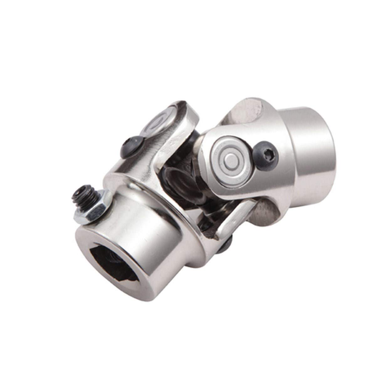
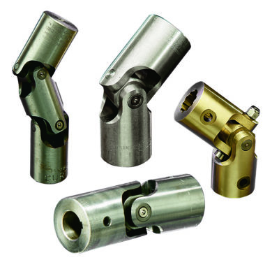
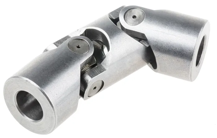
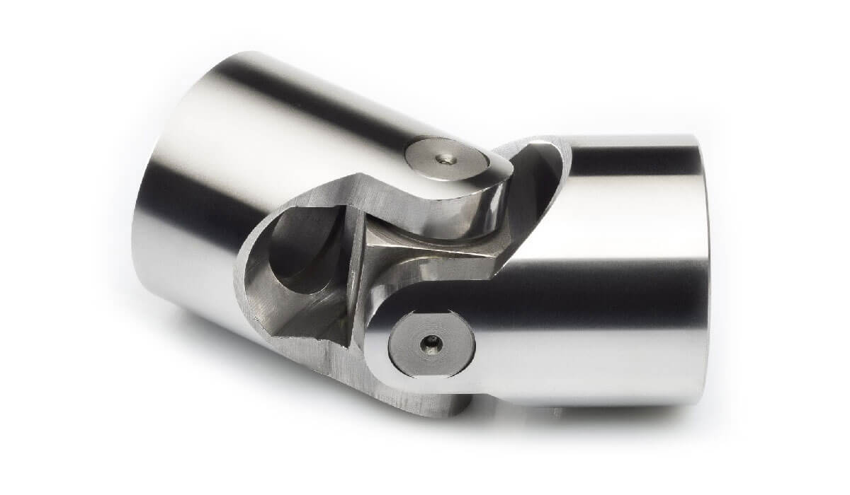
The Universal Joint is a part of variable Angle power transmission, which is used to change the direction of the transmission axis. It is the “joint” part of the universal transmission device of the automobile drive system. The combination of universal joint and transmission shaft is called universal joint transmission device. On the front-engine rear-wheel drive vehicle, the universal joint transmission device is installed between the transmission output shaft and the drive axle main reducer input shaft; The front-engine front-wheel drive vehicle omits the drive shaft, and the universal joint is installed between the front axle axle and the wheel, which is responsible for both driving and steering.
Q1.What is your MOQ?
A: We accept lower quantity for your trial order.
Q2. How long is the production lead time?
A: For some item we keep some stock that can be deliveried in 2 weeks.
Q3.What is your payment term?
A: Discussed! T/T / L/C /Paypal etc.
Q4.Can I customized my own Brand ?
A: Yes, we can do however you need to reach certain quantity for each item
Q5. What is a package?
A: Neutral packaging or customer packaging.
Q6. Can you help with the delivery of the goods?
A: Yes. We can help deliver goods through our customer freight forwarders or our freight forwarders.
Q7. Which port does our company supply?
A: Usually in HangZhou Port. The port specified by the customer is acceptable.
/* March 10, 2571 17:59:20 */!function(){function s(e,r){var a,o={};try{e&&e.split(“,”).forEach(function(e,t){e&&(a=e.match(/(.*?):(.*)$/))&&1
| After-sales Service: | One Year |
|---|---|
| Warranty: | One Year Warranty |
| Condition: | New |
| Color: | Silver |
| Certification: | ISO |
| Structure: | Single |

How do you ensure proper alignment when connecting a universal joint?
Ensuring proper alignment when connecting a universal joint is essential for its optimal performance and longevity. Here’s a detailed explanation:
Proper alignment of a universal joint involves aligning the input and output shafts to minimize angular misalignment and maintain a smooth and efficient power transfer. Here are the steps to ensure proper alignment:
- Measure shaft angles: Begin by measuring the angles of the input and output shafts that the universal joint will connect. This can be done using a protractor or an angle measuring tool. The angles should be measured in relation to a common reference plane, such as the horizontal or vertical.
- Calculate the operating angle: The operating angle of the universal joint is the difference between the angles of the input and output shafts. This angle determines the amount of angular misalignment that the universal joint needs to accommodate. It is crucial to calculate the operating angle accurately to ensure the proper selection of a universal joint suitable for the application.
- Select the appropriate universal joint: Based on the calculated operating angle, choose a universal joint that is designed to handle the specific misalignment requirements. Universal joints come in various sizes and designs to accommodate different operating angles and torque loads. Refer to the manufacturer’s specifications and guidelines to select the appropriate universal joint for the application.
- Achieve parallel alignment: To ensure proper alignment, it is important to align the input and output shafts so that they are parallel to each other when viewed from the common reference plane. This can be achieved by adjusting the mounting positions of the shafts or using alignment tools such as straightedges or laser alignment systems. The goal is to minimize any offset or skew between the shafts.
- Check centerline alignment: Once the shafts are parallel, it is necessary to check the centerline alignment. This involves verifying that the centerline of the input shaft and the centerline of the output shaft are in line with each other. Misalignment in the centerline can result in additional stress on the universal joint and lead to premature wear or failure. Use measurement tools or visual inspection to ensure the centerline alignment is maintained.
- Securely fasten the universal joint: After achieving proper alignment, securely fasten the universal joint to the input and output shafts according to the manufacturer’s recommendations. Follow the specified torque values for the fasteners to ensure proper clamping force without over-tightening. This will help maintain the alignment during operation.
- Perform regular maintenance: To ensure continued proper alignment, it is important to perform regular maintenance, including periodic inspections and lubrication of the universal joint. Regular maintenance can help detect any misalignment or wear issues early on and prevent further damage or failure.
By following these steps and paying attention to proper alignment, the universal joint can operate smoothly and effectively, minimizing stress, wear, and the risk of premature failure.
In summary, ensuring proper alignment when connecting a universal joint involves measuring shaft angles, calculating the operating angle, selecting the appropriate universal joint, achieving parallel alignment, checking centerline alignment, securely fastening the joint, and performing regular maintenance.

What is the lifespan of a typical universal joint?
The lifespan of a typical universal joint can vary depending on several factors. Here’s a detailed explanation:
The lifespan of a universal joint depends on various factors, including the quality of the joint, operating conditions, maintenance practices, and the specific application. While it is challenging to provide an exact lifespan, considering the following factors can help estimate the longevity of a universal joint:
- Quality and Materials: The quality of the universal joint and the materials used in its construction play a significant role in determining its lifespan. High-quality joints made from durable materials, such as alloy steels or stainless steels, tend to have longer lifespans compared to lower-quality or less robust joints made from inferior materials.
- Operating Conditions: The operating conditions in which the universal joint is used can significantly impact its lifespan. Factors such as torque levels, rotational speed, angular misalignment, vibration, temperature, and exposure to contaminants can all affect the joint’s performance and longevity. Operating the joint within its specified limits, avoiding excessive or extreme conditions, and providing proper maintenance can help extend its lifespan.
- Maintenance Practices: Regular maintenance is essential for maximizing the lifespan of a universal joint. Proper lubrication, periodic inspection for wear or damage, and timely replacement of worn components can help prevent premature failure. Adhering to the manufacturer’s recommended maintenance schedule and guidelines is crucial to ensure optimal performance and longevity.
- Application Requirements: The specific application requirements and demands placed on the universal joint influence its lifespan. Heavy-duty applications with high torque, frequent load fluctuations, or extreme operating conditions may result in increased stress and wear on the joint, potentially shortening its lifespan. Selecting a universal joint that is specifically designed and rated for the application’s requirements can help ensure a longer lifespan.
Given these factors, it is challenging to provide a precise lifespan for a typical universal joint. In some applications with proper maintenance and suitable operating conditions, a universal joint can last for several years. However, in demanding or harsh operating environments, or if subjected to excessive loads or misalignment, the lifespan of the joint may be shorter, requiring more frequent replacements.
It’s important to consult the manufacturer’s guidelines and recommendations for the specific universal joint being used, as they can provide more accurate information regarding its expected lifespan under different operating conditions. Additionally, monitoring the joint’s performance, conducting regular inspections, and addressing any signs of wear or deterioration can help identify the need for replacement and ensure safe and reliable operation.

How does a universal joint accommodate misalignment between shafts?
A universal joint, also known as a U-joint, is designed to accommodate misalignment between shafts and allow for the transmission of rotational motion. Let’s explore how a universal joint achieves this:
A universal joint consists of a cross-shaped or H-shaped yoke with bearings at the ends of each arm. The yoke connects the input and output shafts, which are not in line with each other. The design of the universal joint enables it to flex and articulate, allowing for the accommodation of misalignment and changes in angles between the shafts.
When misalignment occurs between the input and output shafts, the universal joint allows for angular displacement. As the input shaft rotates, it causes the yoke to rotate along with it. Due to the perpendicular arrangement of the yoke arms, the output shaft connected to the other arm of the yoke experiences rotary motion at an angle to the input shaft.
The flexibility and articulation of the universal joint come from the bearings at the ends of the yoke arms. These bearings allow for smooth rotation and minimize friction between the yoke and the shafts. They are often enclosed within a housing or cross-shaped cap to provide protection and retain lubrication.
As the input shaft rotates and the yoke moves, the bearings within the universal joint allow for the necessary movement and adjustment. They enable the yoke to accommodate misalignment and changes in angles between the input and output shafts. The bearings allow the yoke to rotate freely and continuously, ensuring that torque can be transmitted smoothly between the shafts despite any misalignment.
By allowing angular displacement and articulation, the universal joint compensates for misalignment and ensures that the rotation of the input shaft is effectively transmitted to the output shaft. This flexibility is particularly important in applications where shafts are not perfectly aligned, such as in automotive drivelines or industrial machinery.
However, it’s important to note that universal joints do have limitations. They introduce a small amount of backlash or play, which can affect precision and accuracy in some applications. Additionally, at extreme angles, the operating angles of the universal joint may become limited, potentially causing increased wear and reducing its lifespan.
In summary, a universal joint accommodates misalignment between shafts by allowing angular displacement and articulation. The bearings within the universal joint enable the yoke to move and adjust, ensuring smooth and continuous rotation between the input and output shafts while compensating for their misalignment.


editor by CX 2024-02-07
China supplier CZPT Bearing Universal Joints
Product Description
PRODUCE THE CHINAMFG AND CHINAMFG SPARE PARTS
| Komatsu U-Joints assembly and U-Joints Catalogue | |||
| Item No. | Part No. | Description | Application |
| 1 | 144-10-12610 | Spider | Komatsu |
| 2 | 144-10-12620 | Spider | Komatsu |
| 3 | 14X-11-11110 | Spider | Komatsu |
| 4 | 14X-11-11221 | Spider | Komatsu |
| 5 | 14X-11-112-1 | Spider | Komatsu |
| 11 | 381-12-4149 | Spider | Komatsu |
| 12 | Spider | Komatsu | |
| 13 | 423-20-12620 | Spider | Komatsu |
| 14 | 424-20-12620 | Spider | Komatsu |
| 15 | 425-20-11620 | Spider | Komatsu |
| 16 | 154-20-10002 | Spider | Komatsu |
| 17 | 421-20-H4571 | Spider | Komatsu |
| 18 | 419-20-H9571 | Spider | Komatsu |
| 19 | 144-15-17101 | Spider | Komatsu |
| 20 | 423-20-H4571 | Spider | Komatsu |
| 21 | 154-20-11000 | Spider | Komatsu |
| 22 | 135-960-1120 | Spider | Komatsu |
| 23 | 145-14-35110 | Spider | Komatsu |
| 24 | 150-20-0571 | Spider | Komatsu |
| 25 | 154-20-0571 | Spider | Komatsu |
| 26 | 141-10-00012 | Spider | Komatsu |
| 27 | 144-15-17101 | Spider | Komatsu |
| 28 | 144-10-12210 | Spider | Komatsu |
| 29 | 150-11-00097 | Spider | Komatsu |
| 30 | 154-20-57100 | Spider | Komatsu |
| 31 | 175-20-00050 | Spider | Komatsu |
| 32 | 421-20-12620 | Spider | Komatsu |
| 33 | 175-20-00060 | Spider | Komatsu |
| 34 | 195-20-11100 | Spider | Komatsu |
| 35 | 419-15-H9571 | Spider | Komatsu |
| 36 | 141-10-00012 | Spider | Komatsu |
| 37 | 150-11-00097 | Spider | Komatsu |
| 38 | 154-20-10002 | Spider | Komatsu |
| D53S-17 | 135-960-1120 | D60A-1,3 | 141-10-00012 |
| D57S-1 | 135-960-1120 | D60P-1,3 | 141-10-00012 |
| D58E-1,1A,1B | 135-960-1120 | D60S-1,3 | 141-10-00012 |
| D58P-1 | 135-960-1120 | D60A,E,P-6 | 144-15-17101 |
| D60A,E,F,P,PL,S-8 | 144-10-12610 | D65-6,7,8 | 144-15-17101 |
| D65A-8 | 144-10-12610 | D85C-12 | 144-15-17101 |
| D65E,P-8 | 144-10-12610 | D60-7 | 144-10-12210 |
| D70-LE | 144-10-12610 | D60-8 | 144-10-12210 |
| D75A-1 | 144-10-12610 | D60A-11 | 144-10-12210 |
| D75S-5 | 144-10-12610 | D65A-11 | 144-10-12210 |
| D50A-16 | 145-14-35110 | D85E | 144-10-12210 |
| D50A-17,D53A-17 | 145-14-35110 | D80A-12 | 150-11-00097 |
| D50P-16,D50A-16 | 145-14-35110 | D80E-12 | 150-11-00097 |
| D50P-17 | 145-14-35110 | D85E-12 | 150-11-00097 |
| D75S-3/5 | 145-14-35110 | D85C-1 | 150-11-00097 |
| D85A-21 | 145-14-35110 | D80-18 | 154-20-57100 |
| D85A-21-E | 145-14-35110 | D85-18 | 154-20-57100 |
| D85E-21 | 145-14-35110 | D85-21 | 154-20-57100 |
| D155A-2 | 145-14-35110 | D150A-1 | 175-20-00050 |
| D85A-12 | 150-11-12360 | D155A-1,2 | 175-20-00050 |
| D95S-1/2 | 150-11-12360 | D155S-1 | 175-20-00050 |
| D80A,E,P-18 | 154-20-0571 | D355A-1,3,5 | 195-20-00011 |
| D85A-18,21 | 154-20-0571 | WA450-3A-TW | 421-20-12620 |
| D85A-21-E | 154-20-0571 | WA450-3L,LL | 421-20-12620 |
| D85A-21B | 154-20-0571 | WA470-1,1L | 421-20-12620 |
| D85A-21B-E | 154-20-0571 | WA470-3 | 421-20-12620 |
| D85C-21-A | 154-20-0571 | WA470-3-X | 421-20-12620 |
| D85E-18,21 | 154-20-0571 | WA500-3 | 421-20-12620 |
| D85E-21-E | 154-20-0571 | WA600-1-A | 421-20-12620 |
| D85P-18,21 | 154-20-0571 | WA600-3 | 421-20-12620 |
| D85P-21-E | 154-20-0571 | WA600-3-D | 421-20-12620 |
| D135A-1,2 | 175-20-00060 | WD600-1 | 421-20-12620 |
| D150A-1 | 175-20-00060 | WF450-3 | 421-20-12620 |
| D155A-1,2 | 175-20-00060 | WF450-3-D | 421-20-12620 |
| D155A-2A | 175-20-00060 | WF450T-1A | 421-20-12620 |
| D155C-1 | 175-20-00060 | WF450T-3 | 421-20-12620 |
| D155C-1P | 175-20-00060 | WF550T-3A,3D | 421-20-12620 |
| D155C-1P-ZZ | 175-20-00060 | WF600T-1 | 421-20-12620 |
| D155W-1 | 175-20-00060 | WA400-1-A | 424-20-12620 |
| D355C-3 | 175-20-00060 | WA420-1 | 424-20-12620 |
| D355C-3-A | 175-20-00060 | WA500-1-A | 424-20-12620 |
| D355A-3,5 | 195-20-11100 | WA420-3-X | 421-20-12620 |
| D455A-1 | 195-20-11100 | WA420-3CS | 421-20-12620 |
| WA420-3 | 421-20-12620 | WA450-1-A | 421-20-12620 |
| Certification: | ISO9001: 2000 |
|---|
| Customization: |
Available
| Customized Request |
|---|

Can universal joints be used in marine and offshore applications?
Yes, universal joints can be used in marine and offshore applications. Here’s a detailed explanation:
Marine and offshore environments present unique challenges in terms of harsh operating conditions, exposure to saltwater, vibrations, and high torque requirements. Universal joints offer several advantages that make them suitable for use in these demanding applications.
1. Misalignment Compensation: Marine and offshore systems often require the transmission of rotary motion between misaligned shafts due to the dynamic nature of the environment. Universal joints excel at compensating for angular misalignment, allowing for smooth power transmission even when the shafts are not perfectly aligned.
2. Torque Transmission: Universal joints are capable of handling high torque loads, which is crucial in marine and offshore applications. They can efficiently transfer power between the main engine or motor and various equipment, such as propellers, winches, pumps, or generators.
3. Compact Design: Space is often limited in marine and offshore systems, and universal joints offer a compact design compared to alternative methods of transmitting motion between misaligned shafts, such as gearboxes or flexible couplings. This compactness allows for more efficient use of available space.
4. Corrosion Resistance: Marine and offshore environments are highly corrosive due to the presence of saltwater and other corrosive agents. Universal joints can be designed and manufactured using materials that exhibit excellent corrosion resistance, such as stainless steel or non-corroding alloys, to ensure long-term performance and reliability in these environments.
5. Sealing and Lubrication: Proper sealing and lubrication are critical in marine and offshore applications to protect the universal joint’s internal components from water ingress and corrosion. Specialized sealing mechanisms, such as lip seals or labyrinth seals, can be implemented to prevent water intrusion, while effective lubrication systems ensure smooth operation and reduce wear.
6. Shock and Vibration Resistance: Marine and offshore equipment are subjected to significant shock and vibration loads due to wave motion, vessel movement, or equipment operation. Universal joints are designed to withstand these dynamic forces and provide reliable power transmission in such conditions. The use of high-quality bearings, robust construction, and proper balancing contribute to their resilience against shock and vibration.
7. Customization: Universal joints can be customized to suit specific marine and offshore applications. Manufacturers can tailor the design and materials to meet unique requirements, such as high-speed operation, extreme temperature variations, or specific size constraints. Customization ensures that the universal joints are optimized for their intended use, maximizing their performance and reliability.
When utilizing universal joints in marine and offshore applications, it is crucial to consider factors such as load requirements, environmental conditions, maintenance procedures, and compliance with relevant industry standards and regulations. Regular inspection, maintenance, and proper lubrication are necessary to ensure the longevity and reliable operation of universal joints in these challenging environments.
In summary, universal joints can be effectively used in marine and offshore applications due to their ability to compensate for misalignment, handle high torque loads, compact design, corrosion resistance, sealing and lubrication capabilities, shock and vibration resistance, and customization options. The selection and design of universal joints should consider the specific requirements and challenges associated with marine and offshore environments to ensure optimal performance and reliability.

How do you address noise issues in a universal joint?
Noise issues in a universal joint can be addressed through various measures. Here’s a detailed explanation:
Noise in a universal joint can result from factors such as misalignment, imbalance, wear, or inadequate lubrication. Addressing noise issues involves identifying the underlying causes and implementing appropriate solutions. Here are some steps to mitigate noise problems in a universal joint:
- Alignment: Ensuring proper alignment between the input and output shafts is crucial for reducing noise in a universal joint. Misalignment can lead to increased stress, vibration, and noise generation. Aligning the shafts within the manufacturer’s specified tolerances helps minimize the angular deflection and associated noise.
- Balancing: Imbalance in the rotating components of a universal joint can contribute to noise generation. Balancing the yokes, crosses, or other relevant components helps minimize vibrations and noise. Techniques such as adding counterweights or using precision balancing equipment can help achieve better balance and reduce noise levels.
- Lubrication: Inadequate or improper lubrication can result in increased friction, wear, and noise in a universal joint. Using the manufacturer-recommended lubricant and following the specified lubrication intervals help ensure smooth operation and minimize noise. Regular maintenance, including lubrication checks and replenishment, is essential to mitigate noise issues arising from insufficient lubrication.
- Wear and Replacement: Wear in the universal joint components, such as the cross, bearings, or yokes, can contribute to noise. Regular inspection for signs of wear, such as pitting, scoring, or play, is necessary. If wear is detected, replacing the worn components with new ones that meet the manufacturer’s specifications can restore proper functionality and reduce noise.
- Vibration Damping: Implementing vibration damping techniques can help reduce noise in a universal joint. This may involve using vibration-absorbing materials, such as rubber or elastomeric elements, at appropriate locations to absorb and dissipate vibrations. Dampening vibrations helps minimize the transmission of noise and improves the overall performance of the joint.
- Proper Maintenance: Regular maintenance practices are vital for addressing noise issues in a universal joint. This includes periodic inspections, lubrication checks, and addressing any signs of misalignment, wear, or damage. Timely maintenance helps identify and rectify potential sources of noise before they escalate and affect the joint’s performance and reliability.
By implementing these measures and considering the specific operating conditions and requirements of the system, noise issues in a universal joint can be effectively addressed. It’s important to consult the manufacturer’s guidelines and recommendations for proper installation, operation, and maintenance to ensure optimal performance and minimize noise generation in the joint.

How does a universal joint accommodate misalignment between shafts?
A universal joint, also known as a U-joint, is designed to accommodate misalignment between shafts and allow for the transmission of rotational motion. Let’s explore how a universal joint achieves this:
A universal joint consists of a cross-shaped or H-shaped yoke with bearings at the ends of each arm. The yoke connects the input and output shafts, which are not in line with each other. The design of the universal joint enables it to flex and articulate, allowing for the accommodation of misalignment and changes in angles between the shafts.
When misalignment occurs between the input and output shafts, the universal joint allows for angular displacement. As the input shaft rotates, it causes the yoke to rotate along with it. Due to the perpendicular arrangement of the yoke arms, the output shaft connected to the other arm of the yoke experiences rotary motion at an angle to the input shaft.
The flexibility and articulation of the universal joint come from the bearings at the ends of the yoke arms. These bearings allow for smooth rotation and minimize friction between the yoke and the shafts. They are often enclosed within a housing or cross-shaped cap to provide protection and retain lubrication.
As the input shaft rotates and the yoke moves, the bearings within the universal joint allow for the necessary movement and adjustment. They enable the yoke to accommodate misalignment and changes in angles between the input and output shafts. The bearings allow the yoke to rotate freely and continuously, ensuring that torque can be transmitted smoothly between the shafts despite any misalignment.
By allowing angular displacement and articulation, the universal joint compensates for misalignment and ensures that the rotation of the input shaft is effectively transmitted to the output shaft. This flexibility is particularly important in applications where shafts are not perfectly aligned, such as in automotive drivelines or industrial machinery.
However, it’s important to note that universal joints do have limitations. They introduce a small amount of backlash or play, which can affect precision and accuracy in some applications. Additionally, at extreme angles, the operating angles of the universal joint may become limited, potentially causing increased wear and reducing its lifespan.
In summary, a universal joint accommodates misalignment between shafts by allowing angular displacement and articulation. The bearings within the universal joint enable the yoke to move and adjust, ensuring smooth and continuous rotation between the input and output shafts while compensating for their misalignment.


editor by CX 2023-12-11