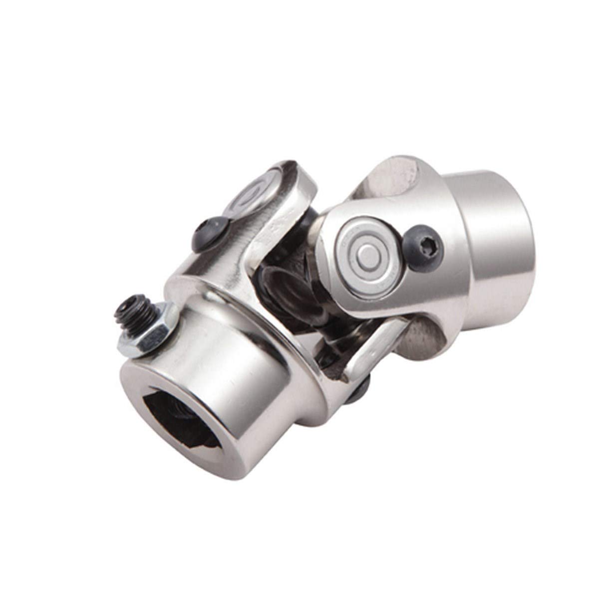
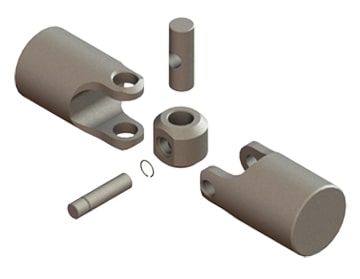
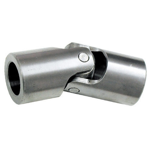
Product Description
| Spicer | P (mm) | R (mm) | Caterpillar | Precision | Rockwell | GKN | Alloy | Neapcon | Serie | Bearing type |
| 5-2002X | 33.34 | 79 | 644683 | 951 | CP2002 | HS520 | 1-2171 | 2C | 4LWT | |
| 5-2117X | 33.34 | 79 | 316117 | 994 | HS521 | 1-2186 | 2C | 4LWD | ||
| 5-2116X | 33.34 | 79 | 6S6902 | 952 | CP2116 | 1063 | 2C | 2LWT,2LWD | ||
| 5-3000X | 36.5 | 90.4 | 5D9153 | 536 | HS530 | 1711 | 3-3152 | 3C | 4LWT | |
| 5-3014X | 36.5 | 90.4 | 9K1976 | 535 | HS532 | 3C | 2LWT,2LWD | |||
| 5-4143X | 36.5 | 108 | 6K 0571 | 969 | HS545 | 1689 | 3-4143 | 4C | 4HWD | |
| 5-4002X | 36.5 | 108 | 6F7160 | 540 | CP4002 | HS540 | 1703 | 3-4138 | 4C | 4LWT |
| 5-4123X | 36.5 | 108 | 9K3969 | 541 | CP4101 | HS542 | 1704 | 3-4123 | 4C | 2LWT,2LWD |
| 5-4140X | 36.5 | 108 | 5M800 | 929 | CP4130 | HS543 | 3-4140 | 4C | 2LWT,2HWD | |
| 5-1405X | 36.5 | 108 | 549 | 1708 | 4C | 4LWD | ||||
| 5-4141X | 36.5 | 108 | 7M2695 | 996 | 4C | 2LWD,2HWD | ||||
| 5-5177X | 42.88 | 115.06 | 2K3631 | 968 | CP5177 | HS555 | 1728 | 4-5177 | 5C | 4HWD |
| 5-5000X | 42.88 | 115.06 | 7J5251 | 550 | CP5122 | HS550 | 1720 | 4-5122 | 5C | 4LWT |
| 5-5121X | 42.88 | 115.06 | 7J5245 | 552 | CP5101 | HS552 | 1721 | 4-5127 | 5C | 2LWT,2LWD |
| 5-5173X | 42.88 | 115.06 | 933 | HS553 | 1722 | 4-5173 | 5C | 2LWT,2HWD | ||
| 5-5000X | 42.88 | 115.06 | 999 | 5C | 4HWD | |||||
| 5-5139X | 42.88 | 115.06 | 5C | 2LWD,2HWD | ||||||
| 5-6102X | 42.88 | 140.46 | 643633 | 563 | CP62N-13 | HS563 | 1822 | 4-6114 | 6C | 2LWT,2HWD |
| 5-6000X | 42.88 | 140.46 | 641152 | 560 | CP62N-47 | HS560 | 1820 | 4-6143 | 6C | 4LWT |
| 5-6106X | 42.88 | 140.46 | 1S9670 | 905 | CP62N-49 | HS565 | 1826 | 4-6128 | 6C | 4HWD |
| G5-6103X | 42.88 | 140.46 | 564 | 1823 | 4-6103 | 6C | 2LWT,2LWD | |||
| G5-6104X | 42.88 | 140.46 | 566 | 1824 | 4-6104 | 6C | 4LWD | |||
| G5-6149X | 42.88 | 140.46 | 6C | 2LWD,2HWD | ||||||
| 5-7105X | 49.2 | 148.38 | 6H2577 | 927 | CP72N-31 | HS575 | 1840 | 5-7126 | 7C | 4HWD |
| 5-7000X | 49.2 | 148.32 | 8F7719 | 570 | CP72N-32 | HS570 | 1841 | 5-7205 | 7C | 4LWT |
| 5-7202X | 49.2 | 148.38 | 7J5242 | 574 | CP72N-33 | HS573 | 1843 | 5-7207 | 7C | 2LWT,2HWD |
| 5-7203X | 49.2 | 148.38 | 575 | CP72N-55 | 5-7208 | 7C | 4LWD | |||
| 5-7206X | 49.2 | 148.38 | 572 | CP72N-34 | 1842 | 5-7206 | 7C | 2LWT,2LWD | ||
| 5-7204X | 49.2 | 148.38 | 576 | CP72N-57 | 5-7209 | 7C | 2LWD,2HWD | |||
| 5-8105X | 49.2 | 206.32 | 6H2579 | 928 | CP78WB-2 | HS585 | 1850 | 6-8113 | 8C | 4HWD |
| 5-8200X | 49.2 | 206.32 | 581 | CP82N-28 | 1851 | 6-8205 | 8C | 4LWT |
/* March 10, 2571 17:59:20 */!function(){function s(e,r){var a,o={};try{e&&e.split(“,”).forEach(function(e,t){e&&(a=e.match(/(.*?):(.*)$/))&&1
| Condition: | New |
|---|---|
| Certification: | ISO, Ts16949 |
| Structure: | Single |
| Material: | 20cr |
| Type: | Universal Joint |
| Transport Package: | Box + Plywood Case |
| Samples: |
US$ 10/Piece
1 Piece(Min.Order) | |
|---|
| Customization: |
Available
| Customized Request |
|---|

What are the safety considerations when working with universal joints?
Working with universal joints requires adherence to certain safety considerations to prevent accidents, injuries, and equipment damage. Here’s a detailed explanation:
When dealing with universal joints, it is important to keep the following safety considerations in mind:
- Proper Training and Knowledge: Ensure that individuals working with universal joints have the necessary training and knowledge of their operation, installation, and maintenance. Familiarity with safety procedures and understanding the potential hazards associated with universal joints is crucial for safe handling.
- Personal Protective Equipment (PPE): Use appropriate personal protective equipment, such as safety glasses, gloves, and protective clothing, when working with universal joints. PPE can provide protection against potential hazards, including sharp edges, pinch points, or flying debris during installation, removal, or maintenance activities.
- Secure the System: Before working on a system that involves universal joints, ensure that the equipment is securely shut down and de-energized. Lockout/tagout procedures should be followed to prevent unexpected energization or movement that could cause injury. Securely support any components or shafts connected to the universal joint to prevent accidental movement or collapse during work.
- Inspect for Damage or Wear: Regularly inspect universal joints for signs of damage, wear, or misalignment. Look for indications of excessive play, corrosion, fatigue, or any other abnormalities that may compromise the joint’s integrity. Replace any worn or damaged components promptly to avoid potential failure during operation.
- Safe Handling: When installing or removing universal joints, use proper lifting techniques and equipment to avoid strain or injury. Universal joints can be heavy and cumbersome, so mechanical assistance or lifting devices may be necessary. Follow safe handling practices and avoid placing hands or body parts in the path of rotating or moving components.
- Avoid Exceeding Design Limits: Universal joints have specific design limits for torque, operating angles, and speed. Ensure that these limits are not exceeded during operation. Exceeding the design limits can lead to premature wear, distortion, or catastrophic failure of the joint. Always consult the manufacturer’s guidelines and specifications to ensure safe operation within the defined limits.
- Lubrication and Maintenance: Proper lubrication is essential for the smooth operation and longevity of universal joints. Follow the manufacturer’s recommendations for lubrication intervals and use the specified lubricants. Regularly inspect and maintain the joint, tightening fasteners as needed and addressing any signs of lubrication breakdown, contamination, or leakage.
- Appropriate Tools and Equipment: Use the correct tools and equipment for working with universal joints. Improper tools or techniques can cause damage to the joint or result in injuries. Ensure that tools are in good condition, properly calibrated, and suitable for the specific task at hand.
- Follow Manufacturer Guidelines: Always follow the manufacturer’s guidelines, instructions, and safety precautions specific to the universal joint being used. Manufacturers provide important information regarding installation, operation, maintenance, and safety considerations that should be strictly adhered to.
By adhering to these safety considerations, individuals can minimize the risk of accidents, injuries, and equipment damage when working with universal joints.

How do you calculate the operating angles of a universal joint?
Calculating the operating angles of a universal joint involves measuring the angular displacement between the input and output shafts. Here’s a detailed explanation:
To calculate the operating angles of a universal joint, you need to measure the angles at which the input and output shafts are misaligned. The operating angles are typically expressed as the angles between the axes of the two shafts.
Here’s a step-by-step process for calculating the operating angles:
- Identify the input shaft and the output shaft of the universal joint.
- Measure and record the angle of the input shaft relative to a reference plane or axis. This can be done using a protractor, angle finder, or other measuring tools. The reference plane is typically a fixed surface or a known axis.
- Measure and record the angle of the output shaft relative to the same reference plane or axis.
- Calculate the operating angles by finding the difference between the input and output shaft angles. Depending on the arrangement of the universal joint, there may be two operating angles: one for the joint at the input side and another for the joint at the output side.
It’s important to note that the specific method of measuring and calculating the operating angles may vary depending on the design and configuration of the universal joint. Some universal joints have built-in methods for measuring the operating angles, such as markings or indicators on the joint itself.
Additionally, it’s crucial to consider the range of acceptable operating angles specified by the manufacturer. Operating a universal joint beyond its recommended angles can lead to increased wear, reduced lifespan, and potential failure.
In summary, calculating the operating angles of a universal joint involves measuring the angular displacement between the input and output shafts. By measuring the angles and finding the difference between them, you can determine the operating angles of the universal joint.

Can you explain the purpose of a universal joint in a drive shaft?
In a drive shaft, a universal joint serves a crucial purpose in transmitting rotational motion between the engine or power source and the driven wheels or other components. Let’s delve into the purpose of a universal joint in a drive shaft:
A drive shaft is a mechanical component that transfers torque from the engine or power source to the wheels or other driven components in a vehicle or machinery. It is typically used in rear-wheel drive and four-wheel drive systems. The drive shaft connects the transmission output shaft to the differential or axle assembly, allowing the wheels to receive power and propel the vehicle forward.
The purpose of a universal joint in a drive shaft is to accommodate the misalignment and changes in angles between the transmission and the differential or axle assembly. Misalignment can occur due to various factors, including the vehicle’s suspension system, the position of the engine, and the movement of the wheels. Without a flexible coupling mechanism, misalignment would cause binding, vibration, and potential damage to the drive shaft and other drivetrain components.
Universal joints provide the necessary flexibility and articulation to compensate for misalignment and changes in angles. They allow the drive shaft to bend and rotate at varying angles while transmitting torque from the transmission to the differential. The universal joint allows the drive shaft to operate smoothly and efficiently, even when the vehicle is in motion and the suspension system causes changes in the relative positions of the transmission and the differential.
When the engine or power source rotates the drive shaft, the universal joint allows angular displacement between the transmission and the differential. As the drive shaft bends and changes angles, the universal joint accommodates these movements, ensuring continuous torque transmission without placing excessive stress on the drivetrain components.
The universal joint consists of a cross-shaped or H-shaped yoke with bearings at the ends of each arm. These bearings allow for smooth rotation and minimize friction between the yoke and the drive shaft. The design of the universal joint enables it to flex and articulate, compensating for misalignment and changes in angles without affecting the rotation of the drive shaft.
Overall, the purpose of a universal joint in a drive shaft is to provide the necessary flexibility and articulation to accommodate misalignment and changes in angles. By allowing the drive shaft to bend and rotate at varying angles, the universal joint ensures smooth and efficient torque transmission between the engine and the driven wheels or components, contributing to the proper functioning of the vehicle or machinery.


editor by CX 2023-12-29